Transcription of Wiring Diagram Book - Daltco
1 Wiring Diagram BookA115B1B21618B3A2B1 B31516 18 Supply voltageLMH2 LevelsB2L1FU1460 VFU2 GNDL3L2H1H3H2H4FU3X1 AFU4FU5X2 ARPowerOnOptional115 VX1X2230 VH1H3H2H4 Optional ConnectionElectrostaticallyShielded TransformerFU6 OFFON M L1L221 OLSTOPMSTART3 STARTSTARTSTOPSTOPFIBER OPTICTRANSCEIVERCLASS 9005 TYPE FTFIBER OPTICPUSH BUTTON,SELECTOR SWITCH,LIMIT SWITCH, OPTIC CABLEELECTRICALCONNECTIONSBOUNDARY SEAL TO BE INACCORDANCE WITH ARTICLE501-5 OF THE NATIONALELECTRICAL CODEHAZARDOUS LOCATIONSNONHAZARDOUS LOCATIONSCLASS I GROUPS A, B, C & DCLASS II GROUPS E, F & GCLASS IIIFIBER OPTIC CABLEL1L2L3135A1 A2T1T2T3246OR DISCONNECT SWITCHL1L2L3 CIRCUIT BREAKERSTARTSTOPMOT*T1T2T3 MMSOLID STATEOVERLOAD RELAY1 CTMMMOTOR3 CTTO 120 VSEPARATECONTROL*OT is a switch that openswhen an overtemperaturecondition exists (Type MFOand MGO only)T1T3 MOTOR32L2T2L3T3T2L11T1131443445354313221 22 Status( or )LocationA115B1B21618B3A2B1 B31516 18 Supply voltageLMH2 LevelsB221221314X1X3 ACL1L2 LOADO rangeX2 GreenAC1592610481214 (+)13 ( )A1/+ 15 25 Z1 Z216 18A2/ Vs26 28A1A2 File 0140 1993 Square D.
2 All rights reserved. This document may not be copied in whole or in part, or trans-ferred to any other media, without the written permission of Square equipment should be serviced only by qualified electrical maintenance personnel, and thisdocument should not be viewed as sufficient instruction for those who are not otherwise qualified tooperate, service or maintain the equipment discussed. Although reasonable care has been taken to pro-vide accurate and authoritative information in this document, no responsibility is assumed bySquare D for any consequences arising out of the use of this NOTICEPLEASE NOTE: QWIK-STOP and ALHPA-PAK are registered trademarks of Square is a registered trademark of the National Fire Protection Table of Contents i Standard Elementary Diagram Symbols.
3 1-3 NEMA and IEC Markings and Schematic diagrams .. 4 Control and Power Connection Table4 Terminology .. 5 Examples of Control Circuits .. 6 2-Wire Control63-Wire Control6-9 Shunting Thermal Units During Starting Period10 Overcurrent Protection for 3-Wire Control Circuits11 AC Manual Starters and Manual Motor Starting Switches .. 12 Class 251012 Class 2511 and 251213 2-Speed AC Manual Starters andIEC Motor 14 Class 2512 and 252014GV1/GV314 Drum 15 Class 260115 DC Starters, Constant and Adjustable 16 Class 7135 and 713616 Reversing DC Starters, Constant andAdjustable Speed .. 17 Class 7145 and 714617 Mechanically Latched Contactors .. 18 Class 819618 Medium Voltage Motor 18-25 Class 819818-25 Solid State Protective Relays.
4 26-27 Class 843026-27 General Purpose Relays .. 28 Class 850128 NEMA Control 29 Class 8501 and 999929 General Purpose Relays .. 30 Class 850130 Sensing Relays .. 30 RM2 LA1/LG130 IEC Relays .. 31-32 IEC D-Line Control Relays31 Class 850132 Type P 33-35 Class 850233-35 Class 870235 Type T Overload 33-35 Class 906533-35 Type S AC Magnetic Contactors .. 36-40 Class 850236-40 IEC Contactors .. 41-42 IEC Contactors and Auxiliary Contact Blocks41 Input Modules and Reversing Contactors42 Type S AC Magnetic Starters .. 43-50 Class 853643-508538 and 853945,491-Phase, Size 00 to 3432-Phase and 3-Phase, Size 00 to 5443-Phase, Size 6453-Phase, Size 7463-Phase Additions and Special Features47-50 Integral Self-Protected Starters.
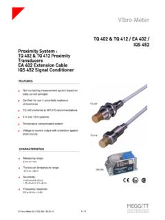
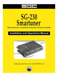
5 51-57 Integral 18 State of Auxiliary Contacts51-52 Integral 32 and 63 State of Auxiliary Contacts53-54 Wiring Diagrams55-57 Type S AC Combination Magnetic Starters .. 58-59 Class 8538 and 853958-593-Phase, Size 0-5583-Phase Additions and Special Features59 Reduced Voltage Controllers .. 60-66 Class 8606 Autotransformer Type60-61 Class 8630 Wye-Delta Type62-63 Class 8640 2-Step Part-Winding Type64 Class 8647 Primary-Resistor Type65 Class 8650 and 8651 Wound-Rotor Type66 Solid State Reduced Voltage Starters .. 67 Class 8660 ALPHA PAK , Type MD-MG67 Solid State Reduced Voltage Controllers .. 68-70 Class 8660 Type MH, MJ, MK and MM68-70 Table of Contents ii Type S AC Reversing Magnetic Starters71-72 Class 873671-722- and 3-Pole713- and 4-Pole72 Type S AC 2-Speed Magnetic Starters73-76 Class 881073-76 Special Control Circuits75-76 Multispeed Motor Connections76-77 1- Phase763-Phase76-77 Programmable Lighting Controllers78 Class 886578 AC Lighting Contactors79-81 Class 890379-81 Load Connections79 Control Circuit Connections80 Panelboard Type Wiring81 Electronic Motor Brakes81-82 Class 8922 QWIK-STOP 81-82 Duplex Motor Controllers82 Class 894182 Fiber Optic Transceivers82 Class 900582 Photoelectric and Inductive Proximity Switches83 Class 900683 Photoelectric and
6 Proximity Sensors84-89 XS, XSC, XSF and XSD84XS and XTA85SG, ST and XUB86 XUM, XUH, XUG, XUL and XUJ87 XUE, XUR, XUD, XUG and XUE S88 XUV89 Limit Switches and Safety Interlocks90-92 Class 900791 XCK and MS92 Pressure Switches and Transducers93 Class 9012, 9013, 9022 and 902593 Level Sensors and Electric Alternators94 Class 9034 and 903994 Pneumatic Timing Relays and Solid State Industrial Timing Relays95-96 Class 905095-96 Timers97 Class 905097 Transformer Disconnects98 Class 907098 Enclosure Selection Guide99 Conductor Ampacity and Conduit Tables100-101 Wire Data102 Electrical Formulas103-104 List of Tables Table 1 Standard Elementary Diagram Symbols 1 Table 2 NEMA and IEC Terminal Markings 4 Table 3 NEMA and IEC Controller Markings and Elementary diagrams 4 Table 4 Control and Power Connections forAcross-the-Line Starters.
7 600 V or less4 Table 5 Motor Lead Connections 64 Table 6 Enclosures for Non-Hazardous Locations 99 Table 7 Enclosures for Hazardous Locations 99 Table 8 Conductor Ampacity100 Table 9 Ampacity Correction Factors 101 Table 10 Adjustment Factors 101 Table 11 Ratings for 120/240 V, 3-Wire,Single-Phase Dwelling Services101 Table 12 AWG and Metric Wire Data 102 Table 13 Electrical Formulas for Amperes, Horsepower, Kilowatts and KVA 103 Table 14 Ratings for 3-Phase, Single-Speed,Full-Voltage Magnetic Controllers for Nonplugglng and Nonjogging Duty 103 Table 15 Ratings for 3-Phase, Single-Speed,Full-Voltage Magnetic Controllers for Plug-Stop, Plug-Reverse or Jogging Duty 104 Table 16 Power Conversions 104 1 Table 1 Standard Elementary Diagram Symbols SWITCHESSELECTORSPUSH BUTTONS MOMENTARY CONTACTPUSH BUTTONS MAINTAINED CONTACTPILOT LIGHTSINSTANT OPERATING CONTACTSTIMED CONTACTSThe Diagram symbols in Table 1 are used by Square D and, where applicable, conform to NEMA (National Electrical Manufacturers Association) InterrupterCircuit Breakersw/ Thermal OLCircuit Breakersw/ Magnetic OLLimit SwitchesFoot SwitchesPressure &Vacuum SwitchesLiquid Level SwitchesTemperatureActuated SwitchesFlow SwitchesSpeed (Plugging)
8 ClosedHeld 3-4 ABPushButtonFreeDepressedFreeDepressed= contact closed2-Position Selector Switch3-Position Selector Switch2-Position Selector Push & (double circuit)MushroomHeadWobbleStickRIllumina ted2 SingleCircuits1 DoubleCircuit ANon Push-to-TestGPush-to-Test(indicate color by letter) action retarded after coil is: Standard Elementary Diagram Symbols 2 INDUCTORSTRANSFORMERSOVERLOAD RELAYSAC MOTORSDC MOTORSWIRINGCAPACITORSRESISTORSSEMICONDU CTORS Table 1 Standard Elementary Diagram Symbols (cont'd)Iron CoreAir CoreAutoIron CoreAir CoreCurrentDual VoltageThermalMagneticSingle Phase3-PhaseSquirrel Cage2-Phase, 4-WireWound RotorArmatureShunt Field(show 4 loops)Series Field(show 3 loops)Commutating orCompensating Field(show 2 loops)
9 Not ConnectedConnectedPowerControlTerminalGr oundMechanicalConnectionMechanicalInterl ockConnectionAdjustableFixedFixedRESH eatingElementHAdjustable,by Fixed TapsRESR heostat,Potentiometer or Adjustable TapsRESD iode or HalfWave RectifierFull WaveRectifierACDC+DCACT unnelDiodeZenerDiodeBidirectionalBreakdo wn DiodePhotosensitiveCellTriacSCRPUTNPNT ransistorBCEPNPT ransistorBCEUJT,N BaseEB2B1 UJT,P BaseEB2B1 Gate Turn-OfThyristorGAK Standard Elementary Diagram Symbols 3 OTHER COMPONENTSSUPPLEMENTARY CONTACT SYMBOLSIEC SYMBOLSSTATIC SWITCHING CONTROL Static switching control is a method of switching electrical circuits without the use of contacts, primarily by solid state devices.
10 To indicate static switching control, use the symbols shown in this table, enclosing them in a diamond as shown. TERMS SPST:Single Pole, Single ThrowSPDT:Single Pole, Double ThrowDPST:Double Pole, Single ThrowDPDT: Double Pole, Double :Normally :Normally :Timed :Timed ClosedPUT:Programmable Unijunction TransistorSCR:Silicon Controlled RectifierTriac:Bidirectional Triode ThyristorUJT:Unijunction Transistor Table 1 Standard Elementary Diagram Symbols (cont'd)BatteryAnnunciatorBellBuzzerHorn , Alarm,Siren, (indicatetype by letters)VMMeter Shunt+ FuseThermocoupleSingle BreakSPST, BreakSingle BreakSPST, BreakSingle BreakSPDTD ouble BreakSingle BreakDPST, 2 BreakSingle BreakDPST, 2 BreakSingle BreakDPDTD ouble BreakPush ButtonsCoilAux.