Transcription of WIRING DIAGRAMS - STANDARD MOTORS - fantech.com.au
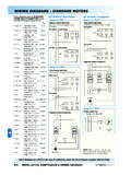
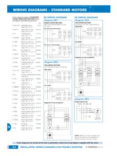
1 Inst Maint & 5/03/2008 10:02 AM Page 6. WIRING DIAGRAMS - STANDARD MOTORS . These DIAGRAMS apply to STANDARD 3 WIRING DIAGRAMS 3 WIRING DIAGRAMS . FRAME INDUCTION MOTORS which are used in the following products:- Diagram DD1 Diagram DD3. Pgs SINGLE SPEED MOTORS TWO-SPEED MOTORS . refer to the name plate data for correct in Dahlander connection (tapped winding). O. Alpha/Beta Series D-4/6. connection High speed Diags. DD 4, 5, 6, 9 L1 L2 L3 E. For delta (D) wired MOTORS Red O. Alpha Series Supply D-34/35 Leads U1 V1 W1. L1 L2 L3 E. Diags. DD 4, 5, 6, 9. W2 U2 V2 Black O. * Centrifugal fans E-14/19 Leads U2 V2 W2. Diags. DD 1, 2, 3 U1 V1 W1. O. * Axial Flow fans B-29/31. Diags. DD 1, 2, 3, 8, 9. O. * Belt-driven axial fans B-29/31 Low speed Diags.
2 DD 1, 2, 3, 7 L1 L2 L3 E. For star (U) wired MOTORS O. * Belt-driven axial fans B-29/31 L1 L2 L3 E. Diags. DD 1, 2, 3, 7, 8 W2 U2 V2. O. Bifurcated fans B-29/31 Red U1 V1 W1. Leads Diags. DD 1, 2, 3, 7, 8 U1 V1 W1. Black O. GE Series D-46/47 Leads U2 V2 W2. Diags. DD 1, 2, 3, 7, 8. Suggested WIRING arrangement O. * Heritage Series D-18/19. Diags. DD 1, 2, 3, 7, 8 L1 L2 L3 N. O. * Heritage Smoke-Spill D-48/49 Diagram DD2. Diags. DD 1, 2, 3. TWO-SPEED MOTORS . O. Compact 2000 A-12/14 with 2 separate windings (dual winding). Diags. DD 1, 4, 5, 6, 9. High speed O. * FA Series D-20/25. L1 L2 L3 E. Diags. DD 1, 2, 3, 7 Red LO SPEED STAR POINT HI SPEED. U1 V1 W1 CONTACTOR CONTACTOR CONTACTOR. Leads O. * FlexLine Series E-3, E-7/11 OVERLOAD OVERLOAD.
3 Diags. DD 1, 2, 3, 7 Black U2 V2 W2. Leads O. * FlexLine Series E-3/6. RED. RED. RED. Diags. DD 1, 2, 3, 7. BLACK. O. * High Capacity Series D-26/27 M BLACK. Diags. DD 1, 2, 3, 7, 8 3~. Low speed BLACK. O. JetVent Axial F-12/13 L1 L2 L3 E. Diags. DD 1, 3. OFF. O. All other JetVents See page M-9. LO HI. O. * Centrifugal fans E-14/19 Red U1 V1 W1. Diags. DD 1, 2, 3 Leads SELECTOR SWITCH. O. * Multiflow Series B-20/24 Black U2 V2 W2. Diags. DD 1, 2, 3, 6, 8 Leads Diagram DD4. O. * PowerLine Series B-16/18 Single speed only Diags. DD 1, 2, 3, 8, 9 Suggested WIRING arrangement Codes: ..31. and ..35. O. * New Generation Series D-10/13 L1 L2 L3 N. L1 L2 L3 N E. Diags. DD 1, 2, 3, 8. U1 - Red O. * Alpha/Beta Industrial D-7/9.
4 Diags. DD 1, 2, 3, 8. V1 - Yellow M. W1 - Blue 3~. O. * New Generation Series D-10/13. Diags. DD 1, 2, 3, 8. Thermal O. New Generation Series D-10/13 LO SPEED HI SPEED Contacts (TB). Diags. DD 1, 2, 3 CONTACTOR CONTACTOR White M. OVERLOAD OVERLOAD. O. * New Generation Series D-10/13. Diags. DD 1, 2, 3, 8. RED. RED. RED. O. * Alpha/Beta Industrial D-7/9 BLACK. Diags. DD 1, 2, 3, 8 M BLACK. 3~ BLACK. O. Short Cased Series B-14/15. Diags. DD 4, 5, 6, 9. OFF. O. * SQ Series A-15/17 LO HI. Diags. DD 1, 2, 3, 8 *NOTE: Refer to the motor manufacturer's data on the motor for WIRING DIAGRAMS on O. Smoke-Spill Series D-26/27 SELECTOR SWITCH. STANDARD frame Ex e, Ex d etc. MOTORS . Diags. DD 1, 2, 3. These DIAGRAMS are current at the time of publication, check the WIRING diagram supplied with the motor.
5 M-6 INSTALLATION, MAINTENANCE & WIRING DIAGRAMS FANTECH 2008. Inst Maint & 5/03/2008 10:02 AM Page 7. WIRING DIAGRAMS - STANDARD MOTORS . 3 WIRING DIAGRAMS 1 WIRING DIAGRAMS 1 WIRING DIAGRAMS . Diagram DD5 Diagram DD6 Diagram DD9. TWO-SPEED MOTORS Anti-Clockwise Clockwise Thermal High speed delta (D) connection L N E. Thermal contacts (TB) L N E contacts (TB). Codes: ..40. to 63. white Z1 M white Z2 M. L1 L2 L3 E W2 or White Cap. 1~ Cap. 1~. U1 or Red L1 L1. U2 or Black M S/C L2. U2. S/C L2. U2. Z1. V1 or Yellow V2 or Orange 3~ L3. Z2. U1 L3 U1. W1 or Blue Thermal Contacts (TB) Z2 - Yellow Z1 - Blue Z2 - Yellow Z1 - Blue White U2 - Black U1 - Red U2 - Black U1 - Red Low speed star (U) connection Bridge L1 and L2 if speed Bridge L1 and L2 if speed controller (S/C) is not required controller (S/C) is not required Codes.
6 40. and upwards L1 L2 L3 E. W2 or White Diagram DD7. U2 or Black V2 or Orange M L N E. 3~. U1 or Red V1 or Yellow W1 or Blue M. Thermal 1~. Contacts (TB). White Diagram DD8. L N E. White L1. S/C L2. Brown M. N. Blue 1~. Bridge L1 and L2 if speed controller (S/C) is not required For all other SINGLE-PHASE WIRING DIAGRAMS refer to the manufacturers data on the motor. M. These DIAGRAMS are current at the time of publication, check the WIRING diagram supplied with the motor. FANTECH 2008 INSTALLATION, MAINTENANCE & WIRING DIAGRAMS M-7. Inst Maint & 5/03/2008 10:02 AM Page 8. WIRING DIAGRAMS - EXTERNAL ROTOR MOTORS . These DIAGRAMS mainly apply to 3 WIRING DIAGRAMS 1 WIRING DIAGRAMS . EXTERNAL ROTOR MOTORS but some STANDARD frame induction motor Diagram ER1 Diagram ER4.
7 TWO-SPEED MOTORS 3 active wires plus auto-reset DIAGRAMS have been included for ease thermal contacts of presentation. Pgs High speed Orange Red Grey L N E. L1 L2 L3 E. O. Gamma Series D-14/17. W2 U2 V2 Brown Diags. ER 1, 2, 4, 5. Brown Blue Black Black M. O. GL Gamma Series D-43/45 U1 V1 W1 Blue 1~. Diags. ER 1, 2, 4, 5 D-57/59. O. Gamma Supply Series D-36/37. Diags. ER 1, 2, 4, 5. O. Compact axial fans B-3. Single-phase MOTORS Low speed Orange Red Grey Codes: to + other fans as shown Diag. ER 6 L1 L2 L3 E. U2. O. EDM Series A-2. W2. Brown Blue V2. Black Diagram ER5. Diags. ER 6, 7 4 active wires plus manual-reset U1 V1 W1 thermal contacts O. EN Series A-3. L N E. Diag. ER 6. Orange L1. O. FlexLine Series E-3/6.
8 Diags. ER 1, 2, 4, 5 S/C L2. Blue Black M. O. Compact F/Proof Series F-3/7 N. Brown 1~. Diag. ER 6 Diagram ER2. O. Filtered Supply Unit A-25 TWO-SPEED MOTORS Thermal Contacts (TB). Series 1; AC MOTORS High speed Yellow Green White White Bridge L1 and L2 if speed Diag. ER 4 L1 L2 L3 E. controller (S/C) is not required W2 U2 V2. O. FSU146 See M-9. Black Blue Brown Codes: and over + other fans as shown O. Sigma Series E-2. U1 V1 W1. Diag. ER 4. Diagram ER6. O. Header Box A-24. Codes: HV-150AE;. Diag. ER 4. MT132; MV112 & MV132. O. HCM Series A-6. Diag. ER 4 Low speed Yellow Green White L N E. L1 L2 L3 E. O. Stylvent Series A-8/9. W2 U2 V2. Diags. ER 6, 8 Black Blue Brown M. O. HXM Series A-11 U1 V1 W1 1~.
9 Diag. ER 6. O. Minitube Series B-12/13. Diags. ER 4, 6. O. Minivent Series D-2/3. Diags. ER 4, 6 D-34/35 Diagram ER7. Diagram ER3 Codes: & ..CR. O. PowerLine Series B-16/18. Diags. ER 1, 2, 3, 4, 5 L N E. L N E. White O. Profile Fan Series D-28/29 L1. Diag. ER 4. S/C L2. Brown M M. O. Ring Plate Series A-4/5. N. Blue 1~ 1~. Diag. ER 4. O. Twin Neta Series B-26/27. Diags. ER 1, 2, 4, 5. O. VentMajor Series B-4/5 Bridge L1 and L2 if speed Diag. ER 6 controller (S/C) is not required Ring Plate Series A-4/5. Diagram ER8. M. O. Diag. ER 4 Codes: HV-230AE & HV-300AE. Exhaust air mode. For supply air O. Delta Series A-22/23 mode bridge LC & LA. Diags. ER 1, 2, 4, 5 L N E. O. Delta Series, Twin fan A-22/23. Diags.
10 ER 1, 2, 4, 5 LC. LB. LA. N. These DIAGRAMS are current at the time of publication, check the WIRING diagram supplied with the motor. M-8 INSTALLATION, MAINTENANCE & WIRING DIAGRAMS FANTECH 2008. Inst Maint & 5/03/2008 10:02 AM Page 9. WIRING DIAGRAMS - ER & INTELLIGENT MOTORS . These DIAGRAMS apply to EXTERNAL 3 WIRING DIAGRAMS 1 WIRING DIAGRAMS . ROTOR MOTORS that are fitted to the following products:- Diagram ER9 Diagram ER10. Pgs TWO SPEED STAR/DELTA MOTOR Codes: All Mixvent units L N E. O. Ezifit In-Wall A-18/19. LA - High Speed Diag. ER 11 U1 1 LB - Low Speed Low LB. O. FSU146 Filtered Supply Units A-26. Speed V1 5. Series 3 LA. 6 Pole Isolating Switch Diag. ER 12 W1 9 N. M. Other FSU units See page M-8.