Transcription of Zimmer Segmental System Distal Femoral Surgical …
1 Zimmer SegmentalSystemDistal Femoral Surgical TechniqueINTROZ immer Segmental System Distal Femoral Surgical Zimmer Segmental System is designed to address significant bone loss resulting from oncology, trauma, and/or the salvage of previously failed arthroplasty. The Segmental Distal Femoral Component features the same condylar-loading geometry as the Zimmer NexGen Rotating Hinge Knee (RH Knee), but will also allow both medial and lateral access to the hinge pin locking assembly. The Segmental One-piece Hinge Post, which is packaged with the corresponding size Segmental Articular Surface, ensures a minimum 40mm jump-height of the post for all sizes of Segmental Articular Surface. The System also includes specific instruments designed to facilitate the Surgical procedure. Femoral Replacement OptionsThe Zimmer Segmental System offers solutions for both Distal Femoral replacement and total Femoral replacement, in addition to proximal tibial replacement (Fig.)
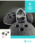
2 1). System CompatibilityThe Segmental Distal Femoral Component may be implanted with all Segmental Distal Femoral Components, the Segmental Trabecular Metal Proximal Tibial Component, Segmental Stems, Segmental Stem Collars, and Segmental Segments as well as the NexGen RH Knee Tibial Components, VerSys Hip System 12/14 Heads and the legacy 12/14 Heads (Fig. 2). The Segmental Distal Femoral Component may be used with both Fluted Stems (cemented) and Variable Stiffness Stems (press-fit) in many stem lengths and diameters. All Stems are compatible with both Trabecular Metal Collars and Tivanium Ti-6Al-4V Alloy Collars (Fig. 2). Variable Stiffness Stems are not indicated for use in the knee with the Segmental Distal Femoral Components in the United 1 INTROZ immer Segmental System Distal Femoral Surgical 2 NexGen KneeSegmental SystemRH KneeNexGen Stem ComponentsTrabecular Metal Femoral ConesRH Knee Distal Femoral and RH Knee Cement Shield Polyethylene Insert ComponentsSegmental Knee Hinge Post and Articular Surface ComponentsSegmental Proximal Tibia Tissue Attachment KitTrabecular Metal Tibial ConesSegmental System Male-Female Segments, Fluted Stems, Variable Stiffness Stems, and Stem CollarsSegmental Intercalary SegmentsSegmental Segments, Straight Stems and Collars(Variable Stiffness Stems are not indicated for use in the knee with the Segmental Trabecular Metal Proximal Tibial Components in the United States)
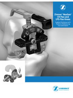
3 NexGen Stem ComponentsNexGen Patellar ComponentsRH Knee Tibial Baseplate ComponentsSegmental Trabecular Metal Proximal Tibial ComponentsSegmental Knee Distal Femoral and Segmental Knee Polyethylene Insert ComponentsSegmental Segments, Stems and Collars(Variable Stiffness Stems are not indicated for use in the knee with the Segmental Distal Femoral Components in the United States) Segmental Proximal Femoral Component (38mm offset) Segmental Trabecular Metal Proximal Femoral Components38mm offset46mm offsetSegmental Trabecular Metal Proximal Femoral Tissue Attachment Femur Replacement Using the Segmental Distal Femoral Component1 Distal Femur Replacement Using the Segmental Distal Femoral Component1 Step One: Prepare the Femur2 Step Two: Prepare the Tibia6 Step Three: Prepare the Patella6 Step Four: Assemble Provisional Components and Perform Trial Reduction6 Step Five: Assemble Implants13 Step Six: Insert Implants16 Disassembly20 Closure20 Zimmer Segmental System Distal Femoral Surgical TechniqueTable of ContentsAPPENDIXPAGEAA ppendix A: NexGen RH Knee & Segmental Articular Surface/Hinge Kit Compatibilities26 SECTIONPAGE2 Using the Segmental One-piece Hinge Post with the NexGen RH Knee21 Using the Segmental One-piece Hinge Post with the NexGen RH Knee21 SECTIONPAGE3 Total Femur Replacement22 Total Femur Replacement22 Proximal Femur Options24 Distal Femoral24 Proximal Tibia25 APPENDIXPAGEBA ppendix B: Servicing the hinge of a well-fixed Segmental Distal Femoral28 SECTION11 Distal Femur Replacement Using the Segmental Distal Femoral ComponentThese conditions may place excessive demand/ severe loading on the polyethylene insert (box) component of the Segmental Distal Femoral Construct.
4 Neuropathic Athropathy (Charcot s knee) Muscle deficiencies (quadriceps insufficiency or previous patellar tendon/tibial tubercle rupture) Refusal to modify postoperative physical activities Morbid obesity (Body Mass Index >39)Premature failure of the Segmental Distal Femoral hinge may be caused by: 1) Stretching of the knee to insert the Segmental Distal Femoral Hinge Post (after back table hinge-post assembly). In vivo assembly is required (Fig. 3). 2) Not replacing the tibial bushing when servicing the hinge at revision (Fig. 4). The tibial bushing is packaged in the Hinge Servicing implant kit and the Tibial Bushing Remover tool 00-5881-055-00 ( ) is in the NexGen RH Knee instrument kits KT-5979-005-00 or 3 Fig. 4 Tibial Bushing1 SECTION2 Distal Femur Replacement Using the Segmental Distal Femoral ComponentTable. 1 Distal Femoral Resection with Stems, Collars and Segments *Each large taper connection adds 2mm to the total length.
5 **Size C Segmental Distal Femoral is 60mm tall. Resect an additional 2mm beyond the total length of resection listed in the table above for the Size 5 Distal Femur**Stem/CollarSegmentsTotal Length*Size B58mm**30mmNone90mm30mm122mm35mm127mm40m m132mm45mm137mm50mm142mm55mm147mm60mm152 mm35+30mm159mm40+30mm164mm40+35mm169mm80 mm172mm40+45mm179mm60+30mm184mm60+35mm18 9mm100mm192mm60+45mm199mm80+30mm204mm80+ 35mm209mm120mm212mm80+45mm219mm100+30mm2 24mm100+35mm229mm140mm232mm100+45mm239mm 120+30mm244mm120+35mm249mm160mm252mm120+ 45mm259mm140+30mm264mm140+35mm269mm180mm 272mm140+45mm279mm30 + 160mm284mm200mm292mm30 + 180mm304mm220mm312mm30 + 200mm324mmStep One: Prepare the Femur After exposing the Distal femur and proximal tibia, extend the leg in a reproducible position (typically full extension). Distal Femoral Resection Measuring from the articular surface of the Distal femur, use a marker, osteotome, or electrocautery to make a horizontal line marking the proposed resection level based on preoperative planning and the implant configuration (Table 1 & Fig.)
6 5). Resect the Distal femur at or slightly Distal ( ) to the marked resection level. Resecting the femur slightly below the mark will account for slightly oblique cuts and help accommodate Femoral resection TIP marking Femoral Rotation outside of the resection area prior to resection for later TIP ensure proper leg length, consider marking both the tibia and femur outside of the resection area. Measure and record the distance between the two lines for later reference during (Size B) Distal Femur**30mmStem/Collar2mm Taper ConnectionSECTION13 Distal Femur Replacement Using the Segmental Distal Femoral ComponentInstrumentsTable. 2bRecommended reamer diametersReam the Femoral Canal Ream the Femoral canal until the reamer contacts cortical bone in the isthmus. For a straight stem, use the straight reamers from the VerSys Hip System . For a bowed stem, flexible reamers from the Pressure Sentinel Intramedullary Reaming System are recommended: use the Pressure Sentinel Reamer Expanded Hip Set (00-2228-000-03) or the ZMR Flexible Reamer Set (00-9975-000-11).
7 If preferred, the flexible reamers can also be used for a straight Variable Stiffness Stem to allow for point contact in the canal. The intramedullary lengths of the stems are listed in the chart to the right (Table 2a). Ream to a depth greater than the intramedullary length to allow proper seating of the stem collar on the cortical bone and placement of a cement restrictor if using a fluted Stiffness Straight Stems For optimal fit, the Segmental 3/4mm Reamers may be used. Flexible reamers may be used to allow for point contact in the canal. If insertion is difficult, consider reaming an additional time with the final reamer diameter : The diameters indicated for the Segmental Variable Stiffness Stems represent the actual outer diameters of the stems, which include the height of the splines. The diameter of the reamed hole should be smaller than the labeled stem size to provide for apposition of the Distal splines with the Femoral canal (Table 2b).
8 When using a bowed variable stiffness stem it may be necessary to ream the intramedullary canal to a diameter equal to or slightly greater than the diameter of the stem to accommodate any difference between the bow of the stem prosthesis and the anatomy of the patient. The diameters indicated for the Segmental Fluted Stems represent the actual outer diameters of the stem. Therefore, the diameter of the definitive stem should be 2mm smaller than that of the largest reamer used to ream the canal to allow for an adequate cement mantle (Table 2b).Stem Size Minimum Ream Diameter (Fluted)Minimum Ream Diameter (Variable Stiffness) 2aStem Types and LengthsStem Diameter (mm)910111213141516171819 Stem IM LengthStem Type130mm Straight (Fluted & Variable Stiffness)190mm Straight (Fluted)190mm Bowed (Variable Stiffness)250mm Bowed (Fluted) Segmental 3/4mm Reamer (See ZSS Profiler)KT-5853-014-00 ZMR System Flexible Reamer (See ZSS Profiler)00-9975-000-11 Pressure Sentinel IM Reamer (See ZSS Profiler)00-2228-000-03 VerSys Hip Reamer (See ZSS Profiler) KT-5853-013-00 00-7899-073-001 SECTION4 Distal Femur Replacement Using the Segmental Distal Femoral ComponentInstrumentsPlane the Femoral Bone Thread the appropriately sized Segmental Planer Pilot (130mm long) for the stem diameter selected onto the Femoral /Tibial Planer (Fig.)
9 6). If the anatomy requires the use of a shorter planer pilot, use the 75mm length Segmental Planer Pilots. If the canal is bowed, use the shorter Planer Pilots from the Segmental Variable Stiffness Stem instrument kit (KT-5853-008-00). A Planer Pilot 1-2mm smaller than the stem diameter chosen can be used to facilitate insertion into a curved medullary canal (Table 3). Attach the assembly to a power driver with a Zimmer adapter. Then plane the resected Distal femur until the cortical bone is smooth and flat. To aid in removing the Planer Pilot from the Planer, insert the pin on the Segmental Collar Provisional Sizer through the cross-hole and, while securing the noncutting end of the planer, turn the shank 6 PlanerPlaner PilotTable. 3 Recommended Planer Pilot DiametersStem SizePlaner Pilot Diameter (Fluted)Planer Pilot Diameter (Variable Stiffness)9mm9mm8mm10mm10mm9mm11mm11mm10 mm12mm12mm11mm13mm13mm12mm14mm14mm13mm15 mm15mm14mm16mm16mm15mm17mm17mm16mm18mm18 mm17mm19mm19mm18mmSegmental Planer Pilot(See ZSS Profiler)00-5851-070-XXSegmental Planer5100-00-052 Segmental Collar Provisional Sizer00-5853-056-10 SECTION15 Distal Femur Replacement Using the Segmental Distal Femoral ComponentInstrumentsCounterbore the Femoral Canal (Variable Stiffness Stems Only) The full diameter of a Variable Stiffness Stem proximal to the splines will be greater than the reamed diameter of the Femoral canal.
10 Counterboring this proximal portion is required for proper insertion of the stem in the intramedullary canal. Thread the appropriate size Counterbore Reamer Tip into the Counterbore Stop Plate (Fig. 7). Then insert the assembly into a power driver. Insert the pin on the Segmental Collar Provisional Sizer through the cross-hole of the Counterbore Reamer Tip and turn the collar to tightly secure it to the Counterbore Stop Plate (Fig. 8). Insert the assembly into the reamed canal and counterbore the proximal canal (Fig. 9). The Counterbore Stop Plate will serve as a stop when the appropriate depth is achieved. Do not over ream or elongate the Reamer Stop PlateCounterbore Reamer TipCounterbore Reamer TipSegmental Collar Provisional SizerFig. 7 Fig. 8 Fig. 9 Counterbore Reamer Tip(See ZSS Profiler)00-5851-073-XXCounterbore Reamer Stop Plate00-5851-073-01 Segmental Collar Provisional Sizer00-5853-056-101 SECTION6 Distal Femur Replacement Using the Segmental Distal Femoral ComponentInstruments30mm20mmDimension AStep Two: Prepare the Tibia For the steps required to prepare the tibia for use with the NexGen RH Knee, refer to the Zimmer NexGen RH Knee Primary/Revision Surgical Technique (97-5880-002-00, revision 4 or later).