Example: bachelor of science
Zybo Z7 Board Reference Manual - Digilentinc
bus @ 1066 MHz • 16 MB Quad-SPI Flash with factory programmed 128-bit random number ... 1.0V differential pairs to XADC ... Note that the PCIe Gen2 controller and Multi-gigabit transceivers are not available on the Zynq-7020 or Zynq-7010 devices.
Tags:
Information
Domain:
Source:
Link to this page:
Documents from same domain

ZedBoard HW Users Guide - Digilent Reference
digilent.comAug 01, 2012 · DDR3 on the PS was routed with 40 ohm trace impedance for single-ended signals, and DCI resistors (VRP/VRN) as well as differential clocks set to 80 ohms. Each DDR3 chip needs its own 240-ohm pull-down on ZQ. DDR-VDDQ is set to 1.5V to support the DDR3 devices selected. DDR-VTT is the termination voltage which is ½ DDR-VDDQ.
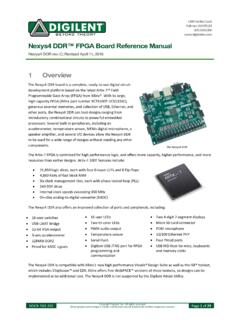
Nexys4 DDR™ FPGA Board Reference Manual - Digilentinc
digilent.comType A USB Host Connector (J5) Serial Prog. Port 2 6-pin JTAG Header (J10) Prog Micro SD Connector (J1) Media Select (JP2) User I/O M2 Mode (JP 1) Programming Mode JP2 JP1 NA SPI Flash NA JTAG USB MicroSD Figure 3. Nexys4 DDR configuration options. Figure 3 shows the different options available for configuring the FPGA. An on-board “mode ...
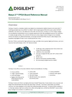
Basys 3™ FPGA Board Reference Manual - Digilent Reference
digilent.comPIC24 Type A USB Host Connector (J2) Serial Prog. Port 2 6-pin JTAG Header (J5) Prog M2 Mode (JP1) Programming Mode JP1 SPI Flash JTAG USB Figure 3. Basys 3 configuration options. The FPGA configuration data is stored in files called bitstreams that have the .bit file extension. The Vivado

Nexys A7 FPGA Board Reference Manual - Digilentinc
digilent.comThe major improvement from the Nexys 4 to the Nexys 4 DDR is the replacement of the 16 MiB Cellular RAM with a 128 MiB DDR2 SDRAM memory. Furthermore, to accommodate the new memory, the pin-out of the FPGA banks changed as well. The audio output (AUD_PWM) needs to be driven open-drain as opposed to push-pull on the Nexys 4. 1 Functional Description

Arty™ FPGA Board Reference Manual - Digilent Reference
digilent.comport (J10) or it can be derived from a 7 to 15 Volt D power supply that [s connected to Power Jack (J12) or Pin 8 of Header J7. Header J13, located between the power jack and the Ethernet connector, is used to determine which source is used. A power-good LED (LD11), driven by the power good _ (PWRGD) output of the ADP5052 regulator, indicates that

Analog Discovery ™ Technical Reference Manual
digilent.com• Spectrum Analyzer - power spectrum and spectral measurements (noise floor, SFDR, SNR, THD, etc.) • Digital Bus Analyzers (SPI, I2C, UART, Parallel) Figure 1. The Analog Discovery. Features include:

ZYBO - Digilentinc
digilent.comMay 31, 2017 · zybo z7 board digilen t inc. a vailable on z20 v er sion only pibtn401 pibtn402 pibtn403 cobtn4 pibtn404 pibtn501 pibtn502 pibtn503 cobtn5 pibtn504 pid101 pid102 pid103 pid104 pid105 cod1 pid201 pid202 pid203 pid204 pid205 cod2 pid301 pid302 pid303 pid304 pid305 cod3 pid401 pid402 pid403 pid404 pid405 cod4 ...

Analog Discovery 2™ Reference Manual
digilent.comStereo audio amplifier to drive external headphones or speakers with replicated AWG signals 16-channel pattern generator (3.3V CMOS, 100Msample/sec)i ii 16-channel virtual digital I/O including buttons, switches, and LEDs – perfect for logic training applicationsiii iv 16-channel digital logic analyzer (3.3V CMOS,
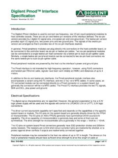
Digilent Pmod Interface Specification
digilent.comhost controller boards. There are six-pin and twelve-pin versions of the interface defined. The six-pin ... Microcontroller system boards are generally provided with dedicated I 2C connectors and provide pull-up resistors that are jumper selectable to be in or out of circuit. FPGA based system boards generally

Introduction to Digital Design Using Digilent FPGA Boards
digilent.comExample 9 – 7-Segment Decoder 48 Example 10 – 7-Segment Displays: x7seg and x7segb 54 Example 11 – 2's Complement 4-Bit Saturator 64 Example 12 – Full Adder 70 ... digital circuit and implement it by connecting the internal gates in a particular way. This
Related documents

ECE 546 Lecture 28 High Speed Links
emlab.uiuc.eduFront Side Bus (Differential, Parallel) ... transceivers. • Ideal PD is a “multiplier” in time‐domain, ex: Mixer • Analog PD High Jitter, noise. • XOR PD sensitive to clock duty cycle • …
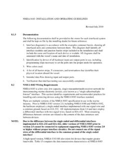
NMEA 0183 INSTALLATION AND OPERATING GUIDELINES
www.navcen.uscg.gova differential interface with two signal wires, based on EIA-422. Most remaining ... NMEA 0183 interfaces are based on a bus topology, where each device connects to the ... 0183 version 1.5 or lower shall only be made using buffers or transceivers that provide opto-isolation and voltage level shifts necessary to protect interface circuitry.
TJA1057 High-speed CAN transceiver
www.nxp.comThe TJA1057 is part of the Mantis family of high-speed CAN transceivers. It provides an interface between a Controller Area Network (CAN) protocol controller and the physical two-wire CAN bus. The transceiver is designed for high-speed CAN applications in the automotive industry, providing the differential transmit and receive capability to (a

UltraScale Architecture System Monitor User Guide
www.xilinx.comtransceivers, and low-cost packaging for an optimum blend of capability and cost-effectiveness. The family is ideal for packet processing in 100G networking and data centers applications as well as DSP-intensive processing needed in next-generation medical imaging, 8k4k video, and heterogeneous wireless infrastructure.