100 Transistor Circuits Go
Found 10 free book(s)
Go to: 1 - 100 Transistor Circuits Go to: 100 IC Circuits
www.radioman33.comIn this Transistor Circuits ebook, we have presented about 100 interesting circuits using transistors and chips. In most cases the IC will contain 10 - 100 transistors, cost less than the individual components and take up much less board-space. They also save a lot of circuit designing and quite often consume less current than discrete components.

RF Power Amplifiers - MIT OpenCourseWare
ocw.mit.edu14 RF IF PA Architectures “Gain stage” is one transistor with passive elements “Active” components often limited to 2 or 3 transistors (gain stages) in signal path Transistor design very important! zMany parallel transistors – often look like mini-circuits themselves Passive components just as important as transistors! zCircuits must be tunable to account for …
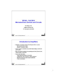
EE105 – Fall 2014 Microelectronic Devices and Circuits
inst.eecs.berkeley.educircuits and inductors by short circuits. – Find Q-point from dc equivalent circuit by using appropriate large-signal transistor model. • ac analysis: – Find ac equivalent circuit by replacing all capacitors by short circuits, inductors by open circuits, dc voltage sources by ground connections and dc current sources by open circuits.
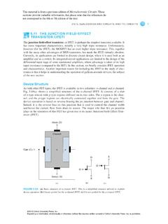
5.11 THE JUNCTION FIELD-EFFECT TRANSISTOR (JFET)
global.oup.comJFETs, GaAs DEVICES AND CIRCUITS, AND TTL CIRCUITS 1 5.11 THE JUNCTION FIELD-EFFECT TRANSISTOR (JFET) The junction field-effect transistor, or JFET, is perhaps the simplest transistor available. It has some important characteristics, notably a very high input resistance. Unfortunately, however (for the JFET), the MOSFET has an even higher input ...

Diodes and Transistors - University of California, Berkeley
inst.eecs.berkeley.eduSo far in EE100 you have seen analog circuits. You started with simple resistive circuits, then dynamical systems (circuits with capacitors and inductors) and then op-amps. Then you learned how circuit elements do not operate the same at all frequencies. Now you will learn about two very important circuit elements – diodes1 and transistors.

ANALOG ELECTRONIC CIRCUITS LAB MANUAL
ssit.edu.inAnalog Electronic Circuits Lab SSIT - 2 - Experiment No: DATE: __/__/____ RC COUPLED AMPLIFIER AIM: -To design a RC coupled single stage FET/BJT amplifier and determination of the gain-frequency response, input and output impedances. APPARATUS REQUIRED:- Transistor - BC 107, capacitors, resistor, power supply, CRO, function

ENGN 2211 Electronic Circuits and Devices Problem Set #8 ...
users.cecs.anu.edu.auENGN 2211 Electronic Circuits and Devices Problem Set #8 BJT CE Amplifier Circuits Q1 Consider the common-emitter BJT amplifier circuit shown in Figure 1. Assume VCC =15 V, β=150, VBE =0.7 V, RE =1 kΩ, RC =4.7 kΩ, R1 =47 kΩ, R2 =10 kΩ, RL =47 kΩ, Rs =100 Ω. RC +VCC R1 R2 RE C1 vs CE C2 Rs RL vin vo Figure 1: The circuit for Question 1 ...

Lecture 4: CMOS Transistor Theory - Pitt
sites.pitt.edu3: CMOS Transistor Theory CMOS VLSI Design Slide 37 Example q We will be using a 0.180 µm process for your project – From TSMC Semiconductor – t ox = 40 Å – µ = 180 cm2/V*s – V t = 0.4 V q Plot I ds vs. V ds – V gs = 0, 0.3,…, 1.8 – Use W/L = 4/2 λ ( ) 14 2 8 3.9 8.85 10 350 120 / ox 100 10 WWW CAV LLL βµ µ − −

Chapter 5 BJT Biasing Circuits - BU
feng.stafpu.bu.edu.egBJT Biasing Circuits 5.1 The DC Operation Point [5] DC Bias: Bias establishes the dc operating point for proper linear operation of an amplifier. If an amplifier is not biased with correct dc voltages on the input and output, it can go into saturation or …
TRANSISTOR : OPERATION MODES - idc-online.com
www.idc-online.comThe actual value of β varies by transistor. It’s usually . around 100, but can range from 50 to 200…even 2000, depending on which transistor you’re using and how much current is running through it. If your transistor had a β of 100, for example, that’d mean an input current