
2600B System SourceMeter SMU Instruments
Series 2600B’s to be inter-connected and function as a single, tightly-synchronized, multi-channel system. The 2600B’s TSP-Link Technology works together with its TSP technology to enable high-speed, SMU-per-pin parallel testing. Unlike other high-speed solutions such as large ATE systems, the 2600B achieves parallel test
Download 2600B System SourceMeter SMU Instruments

Information
Domain:
Source:
Link to this page:
Documents from same domain

P5200A Series High Voltage Differential Probes ...
download.tek.comHigh Voltage Differential Probes Installation and Safety Instructions & Product Documentation CD ZZZ *P071288902* 071-2889-02. ... To disconnect the probes, first disconnect the probe from the circuit. Next, turn ... P5200A Series High Voltage Differential. P5200A.
TDP0500 & TDP1000 High Voltage Differential Probes ...
download.tek.comWarranty Tektronix warrants that this product will be free from defects in materials and workmanship for a period of one (1) year from the date of

Analyzing 26-53 GBaud PAM4 Optical and Electrical Signals
download.tek.comWWW.TEK.COM | 7 Analyzing 26-53 GBaud PAM4 Optical and Electrical Signals APPICATIO OTE 3. Debugging PAM4 Systems and Transceivers Testing a transceiver for compliance to the specified

Understanding and Performing MIPI D-PHY Physical Layer ...
download.tek.comfrom a miniature circuit, the probes with a wide range of accessories like miniature tips, micro clips, solder-tips, etc are needed. For example, a P7360 probe with square pin adapter, and a probe-tip of P6780 (Partnumber 020-3035-00, kit of 15 …
(Courtesy of Tektronix)
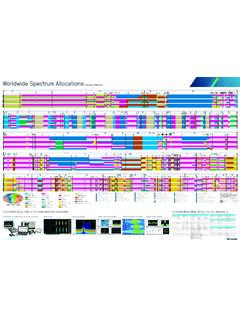
download.tek.comCELLULAR NETWORKS GENERATION TECHNOLOGY CHANNEL SPACING COMMON FREQUENCIES 5G NR - FR1 (New Radio - Frequency Range 1) 5 MHz 10 MHz 15 MHz 20 MHz 25 MHz 30 MHz 40 MHz 50 MHz 60 MHz 70 MHz ... 2100 MHz (IMT) 2300 MHz (S-Band) 2500 MHz (S-Band/BRS) 2600 MHz (IMT-E) 3500 MHz (C-Band) 3700 MHz (C-Band) 4700 MHz (C …
Model 2700 Multimeter/Switch System User's Manual
download.tek.comA good safety pr actice is to expect that hazardous voltage is present in any unknown circuit before measuring. Operators of this product must be protec ted from electric shock at all times. The responsible body must ensure that operators are prevented access and/or insulated from ever y connection point. In some cases, connections must be

2110 5½-Digit Dual-Display Digital Multimeter
download.tek.comRTD and NTC Thermistor Measurements: Accuracy ±0.8˚C, 1 year, exclusive of lead accuracy. PT100, D100, F100, PT385, PT3916, SPRTD (R-Zero, A4, B4, Ax, Bx, Cx, and Dx), NTCT (A, B, and C), and user-definable RTD. CAPACITANCE CHARACTERISTICS Range Test Current Accuracy1 ±(% of reading + % of range) 1 Year, 23° ±5°C 1000. nF 10 µA 2.0 + 0 ...

Datasheet KickStart
download.tek.comPlot and view multiple channels in a single graph with KickStart’s Data Logger App. Create personalized labels for each channel of your data logging switch card. DUT n DUT 2 DUT 1 The Data Logger app aids in the quick setup and control of …

Model 2000 6½-Digit Multimeter
download.tek.comA T ektr onix Company Datasheet Model 2000 6.5 Digit Multimeter DC OPERATING CHARACTERISTICS 2 Function Digits Readings/s PLCs 8 DCV (all ranges), 6½ 3, 4 5 10 DCI (all ranges), and 6½ 3, 7 30 1 Ohms (<10M range) 6½ 3, 5 50 1 5½ 3, 5 270 0.1 5½ 5 500 0.1 5½ 5 1000 0.04 4½ 5 2000 0.01 DC SYSTEM SPEEDS 2, 6 RANGE CHANGE 3: 50/s. FUNCTION …

オシロスコープのすべて - Tektronix
download.tek.com4 www.tektronix.com/ja/oscilloscopes 入門書 光電池 光源 図1 . .オシロスコープを使用した科学データ収集の例 はじめに 海の波 ...
Related documents
`Ohm’s Law III -- Resistors in Series and Parallel - University …
www.phys.utk.eduOhm’s Law III—Resistors in Series and Parallel connected in parallel can be found using the same general procedure and will result in the relationship N Tii=1 1 = RR ∑1. (21) In circuits with combinations of resistors in series and parallel, the total resistance can be
Electrical Circuits - University of Washington
sites.math.washington.eduSimple Series or Parallel Circuits For simple circuits, such as those used in math textbooks to introduce systems of equations, it is often sufficient to use series and parallel relationships to simplify circuits. With this done, Ohm’s Law (V=RI) can be used to find voltages or currents.
AC Electrical Circuit Analysis - MVCC
www2.mvcc.eduChapters on series, parallel and series-parallel RLC circuits commence. Following these, network theorems along with nodal and mesh analysis are discussed for the AC case. The text completes with chapters on AC power, resonance, and introductions to polyphase systems and magnetic circuits.

EE301 - PARALLEL CIRCUITS AND KIRCHHOFF’S CURRENT …
www.usna.eduHomes and ships are usually wired in parallel instead of in series. The reason: The parallel circuit will continue to operate even though one component may fail open. All components can operate at rated voltage independent of other loads when wired in parallel. Series - Parallel Circuits Circuits may contain a combination of series and parallel ...
Experiment 4 ~ Resistors in Series & Parallel
www.umsl.eduparallel, and one with some of each. You will be building circuits similar to the ones you will be working with in homework and exam problems. This experiment should show you the difference between resistors in series and parallel. If you understand what we are doing in this experiment, you will be all set to do well on the midterm questions ...

Lab Report 2 RLC Circuits - obaidtech.com
www.obaidtech.comThen we had to connect them in parallel and nd the values; the connections were made as shown in the gure below: Figure 2: After nding the related values we had to construct the phasor diagrams. 4.3 Exercise 3 - Resonance of series RLC circuits Finally we were required to observe the e ects of resonance frequency in a series RLC circuit.
RC and RL Circuits - Cleveland Institute of Electronics
cie-wc.eduMay 03, 2011 · RC and RL Circuits Rules to remember •ELI the ICE man: Voltage (E) leads Current (I) in an Inductive (L) circuit , whereas Current (I) leads Voltage (E) in a Capacitive (C) circuit –This is only true for SERIES circuits. When it goes into a parallel configuration, the opposite occurs •Current leads Voltage in a Parallel Inductive circuit