AutoCAD 2020 Tutorial Second Level
AutoCAD 3D construction environment, we will create the wireframe model using only the default UCS system, which is aligned to the world coordinate system. Repositioning and/or reorienting the User Coordinate System can be useful in creating 3D models. However, it is also feasible to create 3D models referencing only a single coordinate system.
Download AutoCAD 2020 Tutorial Second Level

Information
Domain:
Source:
Link to this page:
Documents from same domain
Introduction to CATIA V5 - SDC Publications
static.sdcpublications.commodifications to solids using these 2D profiles. You can access the Sketcher ... The projection should now be yellow (this means it is associated with the part and will change with the part) and dashed (this means it is a ... Select the Isometric View icon. This icon is located in the bottom toolbar area. 3) ...
EXPLORING PERSPECTIVE HAND DRAWING
static.sdcpublications.comDrawing an object in perspective provides a realistic view and is therefore an important type of drawing for the interior designer. To view a box in a . one-point perspective, hold it with a flat front facing you and so the two sides appear to move toward a single point in the distance. The surface area of the picture, or the . picture plane,
CATIA V5 Workbook - SDC Publications
static.sdcpublications.comAnother purpose of the general introduction is to present the user with enough information to promote self-discovery of CATIA V5. The following is a guide to what the Review Questions and Practice Exercises will be testing for. You should know the following: - How to select any workbench. - How to tell which CATIA V5 document is current/active.
A Step-by-Step Project Based Approach Utilizing 3D Solid ...
static.sdcpublications.com• SOLIDWORKS is an easy to learn design and analysis tool (SOLIDWORKS Simulation, SOLIDWORKS Motion, SOLIDWORKS Flow Simulation, Sustainability, etc.), which makes it possible for designers to quickly sketch 2D and 3D concepts, create 3D parts and assemblies and detail 2D drawings.
![Engineering Graphics Essentials [4th Edition]](/cache/preview/5/f/2/c/9/7/7/c/thumb-5f2c977c49c57cf1f6e1b8387a99c3df.jpg)
Engineering Graphics Essentials [4th Edition]
static.sdcpublications.com1.1) INTRODUCTION TO ENGINEERING GRAPHICS Engineering graphics is a set of rules and guidelines that help you create an engineering drawing. An engineering drawing is a drawing or a set of drawings that communicates an idea, design, schematic, or model. Engineering drawings come in many forms. Each engineering field has its own type of ...

Learning Autodesk Inventor 2020 - SDC Publications
static.sdcpublications.comthe geometric definitions of the design, such as dimensions, can be varied at any time in ... The approach of creating two-dimensional sketches of the three-dimensional features is ... and locations of all geometric entities defining the design, which …
Tutorial Guide to AutoCAD 2021 - SDC Publications
static.sdcpublications.comTutorial Guide to AutoCAD 2021 2D Drawing, 3D Modeling ® Shawna Lockhart For Microsoft® Windows® SDC PUBLICATIONS www.SDCpublications.com Better Textbooks. Lower Prices.

Autodesk Revit 2018 MEP Fundamentals - SDC Publications
static.sdcpublications.comHint: Measuring Tools When modifying a model, it is useful to know the distance between elements. This can be done with temporary dimensions, or more frequently, by using the measuring tools found in the Quick Access Toolbar or on the . Modify. tab> Measure panel, as shown in Figure2–9. Figure2–9 • (Measure Between Two References): Select two

Tutorial Guide to AutoCAD 2019 - SDC Publications
static.sdcpublications.comin Figure 2.4. It opens with its own defaults for Grid, Snap, and other features. These settings are saved in the drawing file. Figure 2.4 . Saving as a New File. The Save As command allows you to save your drawing to a new file name and/or different drive or folder. You can select this command from the Application icon or from the Quick Access ...

CATIA V5 Tutorials - SDC Publications
static.sdcpublications.com4-2 CATIA V5 Tutorials in Mechanism Design and Animation Introduction In this tutorial you create a slider crank mechanism using a combination of revolute and cylindrical joints. You will also experiment with additional plotting utilities in CATIA. 1 Problem Statement
Related documents
AutoCAD Civil 3D Manual - Geo-Tiff.com
geo-tiff.comMay 30, 2013 · AutoCAD Civil 3D Manual MGEO 2014 1 Foreward . The following document was produced with the Marine Geomatics instructor, Brian Pyke in mind. From my experience observing the Marine Geomatics class of 2014 I would say AutoCAD is the number one most used softwar e by hydrographers. This is

AUTOCAD ELECTRICAL study material
www.msmetoolroomkolkata.comAutoCAD. They can be in 2D or 3D. Even before the construction work begins, one can get an idea, a feel of the building and its premises by observing the AutoCAD 3D drawings. Autodesk Revit version is meant exclusively for architects. Buildings and models can be digitally constructed by using Autodesk Revit.
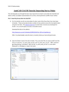
AutoCAD Civil 3D Tutorial: Importing Survey Points
courses.washington.eduCEE 317 GeoSurveying AutoCAD Civil 3D Tutorial: Importing Survey Points This tutorial guides you through the basic steps required to (1) import survey data into AutoCAD and build a surface, (2) explore representations of a surface, and (3) generate a profile of your surface.
Tutorials - Autodesk
images.autodesk.comContents Chapter 1 Welcome to the AutoCAD Civil 3D Tutorials . . . . . . . . . . . . 1 Getting More Information . . . . . . . . . . . . . . . . . . . . . . . . . 2
AutoCAD 3D ハンドブック - Autodesk
images.autodesk.com6 AutoCAD と Autodesk Design Suite オートデスクを代表する AutoCAD は、2D 作図だけでなく、3D 機能を併せ持つ、設計対象や業種を問わ
De-Mystifying AutoCAD Plant 3D Isometrics
villagebim.typepad.comfor isometrics is the Default theme. While the default theme governs general output, Plant 3D provides Override themes to change the display for specific sets of items. Using a combination of the Default theme and override themes, give Plant 3D isometrics a wide range of customization. Theme Editing is available in part in the Title block setup.

Using Hydraflow Storm Sewers Extension with AutoCAD Civil ...
www.cadmasters.comUSING HYDRAFLOW STORM SEWERS EXTENSION WITH AUTOCAD CIVIL 3D 2008 4 Civil 3D Pipe Networks To begin the stormwater pipe design and analysis, create a preliminary pipe network in Civil 3D. At this point, you should already have developed your surface and established any alignments and profiles for your site. To create a preliminary pipe network: 1.