Autodesk Inventor Tutorials
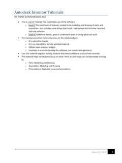
Autodesk Inventor Tutorials Jim Shahan (jcshahan@iastate.edu) March 22, 2014 1 This is a set of Tutorials that cover Basic use of the Software
Download Autodesk Inventor Tutorials

Information
Domain:
Source:
Link to this page:
Documents from same domain

1.0 The Admittance Matrix C - Iowa State University
home.engineering.iastate.edu1 The Power Flow Equations 1.0 The Admittance Matrix Current injections at a bus are analogous to power injections.The student may have …
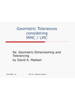
Geometric Tolerances considering MMC / LMC
home.engineering.iastate.eduGeometric Tolerances considering MMC / LMC Re. Geometric Dimensioning and Tolerancing by David A. Madsen. 9/21/2009 - jcs GDT III - Material condtions Material Condition ... ison of geometric tolerances at different produced sizes between MMC and LMC for the various applications.
Comparisons Between the UASB and the EGSB Reactor …
home.engineering.iastate.edu1 Comparisons Between the UASB and the EGSB Reactor Seung J. Lim ABSTRACT Some characteristics of Upflow Anaerobic Sludge Blanket (UASB), Expended Granule Sludge Blanket
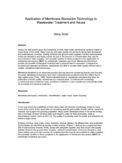
Application of Membrane Bioreactor Technology to ...
home.engineering.iastate.eduwastewater treatment and reuse. Figure 1: Areas Stressed due to Water Demand (World Resources Institute, 2003) The recycling or reuse of wastewater is …

Chapter 1 Wind Turbine Components - Iowa State University
home.engineering.iastate.eduWind Turbine Components I Introduction Wind Turbines can be classified in two categories based on rotor structure. Vertical axis wind turbines have a main shaft that stands perpendicular to the direction of the wind stream. Horizontal axis wind turbines have a main shaft that lies along the direction of the wind stream.

Virtuoso Visualization and Analysis XL User Guide
home.engineering.iastate.eduVirtuoso Visualization and Analysis XL User Guide Product Version 6.1.5 January 2012
Power System Simulation for Engineers (PSS/E version 30)
home.engineering.iastate.edumodeling delta-Y grounded, these will be zero. RG2, Xg2 are for impedance to ground on secondary side and since you are assuming secondary is solidly grounded, these are zero. R01 and X01 are the zero sequence impedance parameters for the transformer and should be entered in pu on the system MVA base.

Allan variance - Iowa State University
home.engineering.iastate.eduAllan variance 1 Allan variance The Allan variance (AVAR), also known as two-sample variance, is a measure of frequency stability in clocks, oscillators and amplifiers. It is named after David W. Allan. It is expressed mathematically as The Allan deviation (ADEV) is the square root of Allan variance.It is also known as sigma-tau, and is expressed ...
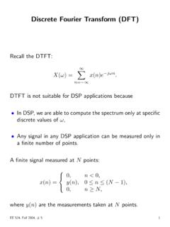
Discrete Fourier Transform (DFT)
home.engineering.iastate.eduDiscrete Fourier Transform (DFT) Recall the DTFT: X(ω) = X∞ n=−∞ x(n)e−jωn. DTFT is not suitable for DSP applications because •In DSP, we are able to compute the spectrum only at specific discrete values of ω, •Any signal in any DSP application can be measured only in a finite number of points. A finite signal measured at N ...
Related documents

DRAWING REQUIREMENTS FOR DEVICE ONNECTOR …
ewcap.uscarteams.orgH OW TO U SE EWCAP D RAWING /D RAFTING R EQUIREMENTS This document is to be used to check newly- released drawings for use by EWCAP. Confirm compliance by …
Fundamentals Handbook Engineering Symbology, Prints, …
www.dieselduck.infoDOE-HDBK-1016/1-93 JANUARY 1993 DOE FUNDAMENTALS HANDBOOK ENGINEERING SYMBOLOGY, PRINTS, AND DRAWINGS Volume 1 of 2 U.S. Department of Energy FSC-6910

Isometric Drawing User Guide - John J. Jacobs
www.john-j-jacobs.deIsometric Drawing User Guide Contents-vii Editing the Isometric_____ 3-7 Inserting a Bill of Materials, Plotting Drawings, and Postprocessing 3-7
Creating 2D Drawings from 3D AutoCAD® Models
www.lukewarmcoffee.comCreating 2D Drawings from 3D AutoCAD® Models Page | 1 Creating 2D Drawings from 3D AutoCAD® Models David Piggott – CrWare, LP GD205-2P This class explores the various techniques in creating 2D part and assembly drawings from 3D AutoCAD models.
P&ID (Piping and Instrumentation Diagram) and …
www.peice.comPIDW102015 PRACTICAL PROFESSIONAL CAREER TRAINING FOR THE OIL & GAS INDUSTRY peice.com C OURSE S YLLABUS Course Agenda Day One 1. Introduction
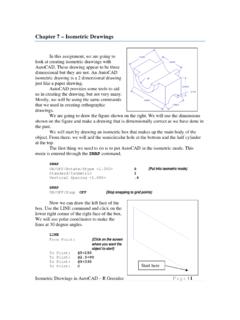
Chapter 7 – Isometric Drawings
www.unm.eduIsometric Drawings in AutoCAD – R Greenlee Page | 1 Chapter 7 – Isometric Drawings In this assignment, we are going to look at creating isometric drawings with
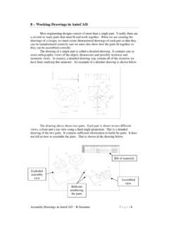
8 – Working Drawings in AutoCAD
www.unm.eduAssembly Drawings in AutoCAD – R Greenlee Page | 2 Note: The assembly views in the drawing above are shown as isometric or pictorial views. This is usually not done in AutoCAD drawings. AutoCAD assembly views are usually