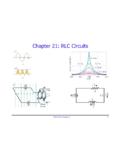
Chapter 21: RLC Circuits
PHY2054: Chapter 21 19 Power in AC Circuits ÎPower formula ÎRewrite using Îcosφis the “power factor” To maximize power delivered to circuit ⇒make φclose to zero Max power delivered to load happens at resonance E.g., too much inductive reactance (X L) can be cancelled by increasing X C (e.g., circuits with large motors) 2 P ave rms=IR rms ave rms rms rms cos
Download Chapter 21: RLC Circuits

Information
Domain:
Source:
Link to this page:
Documents from same domain

PHY4604, Introduction to Quantum Mechanics
www.phys.ufl.eduIntroduction to Maple by Andre Heck † Course Description: An introduction to the quantum theory, as formulated in the 1920’s and 1930’s by Born, Bohr, Schr˜odinger,

PHY4604{Introduction to Quantum Mechanics Fall …
www.phys.ufl.eduPHY4604{Introduction to Quantum Mechanics Fall 2004 Final Exam SOLUTIONS December 17, 2004, 7:30 a.m.- 9:30 a.m. No other materials allowed. If you can’t do one part of a problem, solve subsequent

PHY 3101: Introduction to Modern Physics, Spring …
www.phys.ufl.edu1 PHY 3101: Introduction to Modern Physics, Spring 2016 Course objective: Our universe follows the rules from two very counter-intuitive and abstract concepts in
1 Range of Projectile Motion - Department of Physics at UF
www.phys.ufl.eduMost of the basic physics textbooks talk about the horizontal range of the projectile motion. It is derived using the kinematics equations: a x = 0 v x = v 0x x = v 0xt a y = g v y = v 0y gt y = v 0yt 1 2 gt2 where v 0x = v 0 cos v 0y = v 0 sin Suppose a projectile is thrown from the ground level, then the range is the distance between the ...

Exam 1 Solution - University of Florida
www.phys.ufl.eduthe plates, i.e. E~ = (Ex,0,0) where Ex = constant, the potential V(x) is a monotonic function of x in going from one plate to the other. Thus, since the potential at plate 1

Hooke’s law in terms of stress and strain is
www.phys.ufl.eduThe volume stress is created by the pressure. P A F volume stress The strain will be the change in volume caused by the pressure V V volume strain

Reflection and Refraction of Light - University of Florida
www.phys.ufl.eduReflection and Refraction of Light 235 18. The cross section can be visualized by considering just the two rays of light on the edges of the beam. If the beam of light enters a new medium with a higher index of refraction,
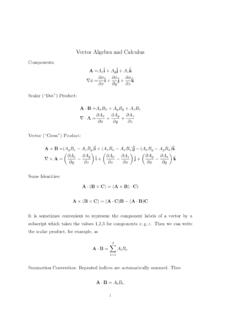
Vector Algebra and Calculus - phys.ufl.edu
www.phys.ufl.eduVector Algebra and Calculus Components: A=Axˆi+Ayˆj+Azˆk ∇φ = ... It is sometimes convenient to represent the component labels of a vector by a subscript which takes the values 1,2,3 for components x,y,z. Then we can write the scalar product, for example, as A·B= X3 i=1 AiBi.

Exam 2 Solutions - University of Florida
www.phys.ufl.eduPHY2054 Spring 2008 4 9. (2054 exam 2 #6, Spring 2007) In the circuit shown, the internal resistance of the battery is 0.1 Ω and the capacitors are initially uncharged. The current (in A) flowing in the 6 Ω resistor an instant after the switch is closed is

Syllabus PHY2053 Spring14 - University of Florida
www.phys.ufl.eduThis site contains the class announcements, the practice homework problems, the course schedule, exam room assignments, and the course syllabus. It also contains previous
Related documents
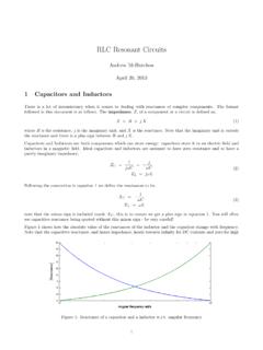
RLC Resonant Circuits - University of Cambridge
mlg.eng.cam.ac.ukTherefore, for series circuits it is in general simpler to calculate the max energy stored by considering the inductor and in parallel circuits by considering the capacitor. Real power is only dissipated in the resistors, P= V Rrms I Rrms = I 2 rms R= V2 Rrms R (16) For the series RLC circuit it is easiest to consider currents, Q(s)! 0 = ! 0 I2 ...
Experiment 4 ~ Resistors in Series & Parallel
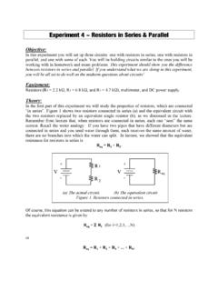
www.umsl.eduExperiment 4 ~ Resistors in Series & Parallel Objective: In this experiment you will set up three circuits: one with resistors in series, one with resistors in parallel, and one with some of each. You will be building circuits similar to the ones you will be working with in homework and exam problems. This experiment should show you the difference
Physics 215 - Experiment 11 Series and Parallel Circuits
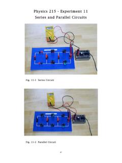
www.phy.olemiss.eduSeries and Parallel Circuits 44 + V - 2 The third type of circuit you will construct is a ccombination circuit (Fig. 11-3 and Fig. 11-6). Resistive elements are not connected in series or parallel. To analyze this type of circuit, it should first be simplified (reduced to an equivalent
`Ohm’s Law III -- Resistors in Series and Parallel
www.phys.utk.eduseries resistance. Wires have resistance that depend on wire size, length, and type of material. Wires add series resistance to circuits, just as good and bad connections add also. In order to fully understand electrical circuits and their behavior, one must first understand Ohm’s Law and the principles regarding resistors in series and parallel
Series and Parallel Circuits - Electronics
cie-wc.eduSeries-Parallel Circuits • Series-Parallel circuits can be more complex as in this case: In circuit (a) we have our original complex circuit. In circuit (b) we have resistors R 1 and R 2 combined to get 13.2Ω. R 4 is in series with the newly combined R 12 and their added value is 51.2Ω. And now (c) we are left with R 124 in parallel with R 3.
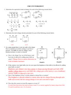
Circuit A Circuit B
www.livingston.orgCIRCUITS WORKSHEET 1. Determine the equivalent (total) resistance for each of the following circuits below. : 2. Determine the total voltage (electric potential) for each of the following circuits below. 13V 12 V 3. In a series circuit there is just one path so the charge flow is constant everywhere (charge is not lost or gained).
Chapter 8 Natural and Step Responses of RLC Circuits
www.ee.nthu.edu.twSeries . RLC . Circuit. 2 Key points What do the response curves of over-, under-, and critically-damped circuits look like? How to choose R, L, C values to achieve fast switching or to prevent overshooting damage? ...

Series -Parallel Circuits - Oakton Community College
www.oakton.eduOverview of Series-Parallel Circuits A series-parallel circuit, or combination circuit, combines both series and parallel connections. Most electronic circuits fall into this category. Series-parallel circuits are typically used when different voltage and current values are required from the same voltage source. Series components form a series ...

Series and parallel combinations
tuttle.merc.iastate.eduEE 201 series/parallel combinations – 12 Breaking down networks using series and parallel R 3 R 4 R 5 R eq R 2 But not all circuits are simple R 1 combinations of series or parallel resistors. The initial example circuit clearly has some things that are in series and some elements that have a parallel-type connection.
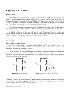
Experiment #1: RC Circuits
courses.physics.ucsd.eduIn more complicated circuits you will need to generalize the notions of series and parallel. For example, in Figure 2, the equivalent resistance of R 4 and R 5 in parallel, 1 R 4 1 R 5 1 R 4 * R 5 R 4 R 5 , is in series with R 3. 1.2 Ohm’s Law Ohm’s Law states that for a resistor the current and voltage are in phase and proportional. That ...