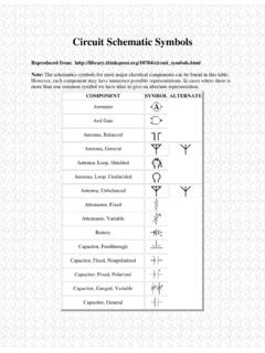
Circuit Schematic Symbols
Ferrite Bead Fuse Galvanometer Ground, Chassis Ground, Earth Handset Headphone, Double Headphone, Single Inductor, Air-Core Inductor, Bifilar Inductor, Iron-Core Inductor, Tapped Inductor, Variable Integrated Circuit Inverter Jack, Coaxial . Jack, Phone, 2-Conductor
Download Circuit Schematic Symbols

Information
Domain:
Source:
Link to this page:
Documents from same domain

Lab7: Elasticity of Materials and Young’s Modulus
mercury.pr.erau.eduLab7: Elasticity of Materials and Young’s Modulus Description In this lab you will measure the Youngs Modulus of a metal wire. In the process, you will gain

Krishna Sampigethaya January 2016 - Mercury WWW …
mercury.pr.erau.eduKrishna Sampigethaya January 2016 2013: Engineer of the Year Award, American Society of Engineers of Indian Origin (ASEI). Award presented by General Charles Bolden Jr., current NASA Administrator and former as-

4 Flow Field Representations A- 5: Unit A-1: Engineering ...
mercury.pr.erau.eduUnit A-1: Engineering Fundamentals Review Page 2 of 15 WHAT IS AERODYNAMICS? Aerodynamics is a branch (means: a specific application) of Fluid Mechanics: (i) Underlying assumption is the fluid as a continuum and, (ii) The working fluid is standard air.CLASSIFICATION OF AERODYNAMICS
Lab 8: Buoyancy and Archimedes Principle
mercury.pr.erau.eduLab 8: Buoyancy and Archimedes Principle Description In this lab, you will explore the force that displacing a fluid (liquid or gas) will exert on the

Mathematics - Elementary Differential Equations
mercury.pr.erau.eduSep 10, 1984 · considerable material on methods of solution, analysis, and approximation that have ... who wishes to emphasize a systems approach to differential equations can take up Chapter 7 (Linear Systems) and perhaps even Chapter 9 (Nonlinear Autonomous ... or for substantial numerical computation, or for extensive symbolic ma-
Related documents
Understanding How Ferrites Can Prevent and Eliminate RF ...
audiosystemsgroup.comnecting the mic to the input gear was wound around a toroidal ferrite (Fig 1) to form an RF choke that reduces that current. Fig 1 – A toroidal ferrite choke Fig 2 – Ferrites are made in many forms To test the effectiveness of ferrite chokes in audio RFI applications, selected product sam-ples were ordered, and a series of tests were run.
ALTERNATIVE 5W STEREO AUDIO AMPLIFIER
www.diodes.comWhen the PAM8406 works without LC filters, it's better to add a ferrite chip bead at the outgoing line of speaker for suppressing the possible . electromagnetic interference. 3. The recommended operating voltage is 5.5V. When the PAM8406 is powered with four battery cells, it should be noted that the voltageof four ...
Understanding and Meeting FPGA Power Requirements White …
www.intel.comrail in the system, a small, cheap filter such as a ferrite bead can be used. In many cases, though, a power converter with sufficiently low output noise is required to deliver a specific, regulated voltage. Traditionally, FPGA board designers have simply used Low Drop-Out linear regulators (LDOs), which
with HD-Wave Technology Installation Guide
www.solaredge.comRemoved Ferrite bead on AC wires l. Addition of link to the Designer web page l. Updated warning about sealing unused power optimizer input connectors l. Output safe voltage is 1V (±0.1V) l. Addition of mounting bracket type 2 l. Mechanical specifications: Addition of inverter models (10kW and 11.4kW) l
EMI Design Guidelines for USB Components
www.ti.comwith ferrite beads. Separate ferrite beads may be used on each VBUS line to each downstream USB connector. Each ferrite bead on the VCC lines should be rated at 500 ma. Separate ferrites are useful, not only for EMI suppression, but also for their series DC resistance which limits the inrush current during a hot plug event.
UltraScale Architecture System Monitor User Guide
www.xilinx.com09/19/2014 1.2 Updated first sentence in SYSMON Overview. Updated placement of ferrite bead in Figure 1-3, Figure 3-19, and Figure 5-1. Added Equation 2-7, Equation 2-8, Equation 2-14, Equation 2-15, Equation 2-17, Equation 2-18, Equation 2-20, and Equation 2-21. Removed timing information from Figure 3-3. Updated SYSMON DRP JTAG Write Operation .