Search results with tag "Ferrite beads"

EMI Design Guidelines for USB Components
www.ti.comwith ferrite beads. Separate ferrite beads may be used on each VBUS line to each downstream USB connector. Each ferrite bead on the VCC lines should be rated at 500 ma. Separate ferrites are useful, not only for EMI suppression, but also for their series DC resistance which limits the inrush current during a hot plug event.
MT-101: Decoupling Techniques - Analog Devices
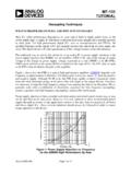
www.analog.comFerrite beads (nonconductive ceramics manufactured from the oxides of nickel, zinc, manganese, or other compounds) are also useful for decoupling in power supply filters. At low frequencies (<100 kHz), ferrites are inductive; thus they are useful in low-pass LC filters. Above 100 kHz, ferrites becomes resistive (high Q).

Reference Only Spec No. JENF243F-0031G-01 EMIFIL (Three ...
www.murata.com② Structure S : Built-in Ferrite Beads Type ③ Style ④ Features ⑤ Temperature Characteristics B3:±10%(-40~+85℃ at 20℃) ⑥ Rated Voltage 2A :2A→100VDC、1H→50VDC ⑦ Capacitance Marked three digits system.(Ex. 22pF→220、22000pF→223) ⑧ Lead Type Q55 : Bulk Lead Type :Straight Lead
OneTechnologyWay P.O.Box9106 Norwood,MA 02062 …
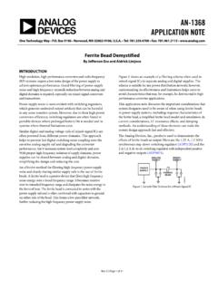
www.analog.comFerrite beads are categorized by three response regions: inductive, resistive, and capacitive. These regions can be determined by looking at a ZRX plot, where Z is the impedance, R is the resistance, and X is the reactance of the bead. To reduce high

TOOLS - Anchor Electronics
anchor-electronics.comferrite beads 3 fuses 2 IC’s 6 inductors 4, 5 LEDs 3 opto isolators 6 resistors 2 switches 5 test clips 6 transistors 5 trimpots 2 voltage reg. 6 Surface Mount INDEX Arduino-related 24 bargain board 17 batteries 7 BNC 18 breadboards 7 bridge rectifiers 15 bumpers 7 cable ties 20 calipers 22 capacitors 12, 13 chemicals 23 & online

with HD-Wave Technology Installation Guide
www.solaredge.comRemoved Ferrite bead on AC wires l. Addition of link to the Designer web page l. Updated warning about sealing unused power optimizer input connectors l. Output safe voltage is 1V (±0.1V) l. Addition of mounting bracket type 2 l. Mechanical specifications: Addition of inverter models (10kW and 11.4kW) l

AVR Microcontroller Hardware Design Considerations
ww1.microchip.comFerrite Bead Another decoupling alternative is to connect the device power and ground pins directly to the planes and connect the decoupling capacitor(s) to the planes as close as possible to the power and ground pins. For large packages, placing decoupling capacitors on the opposite side of the board may be the best way of

Understanding and Meeting FPGA Power Requirements White …
www.intel.comrail in the system, a small, cheap filter such as a ferrite bead can be used. In many cases, though, a power converter with sufficiently low output noise is required to deliver a specific, regulated voltage. Traditionally, FPGA board designers have simply used Low Drop-Out linear regulators (LDOs), which
TPA3110D2 15-W Fil ter-Free Stereo Class-D Audio Power ...
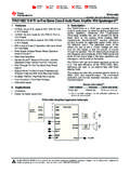
www.ti.comTechnology enables the use of inexpensive ferrite bead filters at the outputs while meeting EMC requirements. SpeakerGuard™ speaker protection circuitry includes an adjustable power limiter and a DC detection circuit. The adjustable power limiter allows the user to set a "virtual" voltage rail lower than the chip supply to limit the amount of ...

AN0046: USB Hardware Design Guidelines
www.silabs.com• Use a ferrite bead for VBUS. Place near receptacle. • Use a switch that can shut off VBUS if current exceeds 500 mA. • Provide at least 96 uF decoupling capacitance on VBUS. Place near USB receptacle. • Terminate D+ and D- with 15 ohm serial resistors. Place near EFM32. • Use an ESD protection device. Place near USB receptacle.
AN4488 Application note - STMicroelectronics
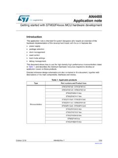
www.st.com–VDDA can be connected to VDD through a ferrite bead. V e h –T REF+ pin can be connected to VDDA through a resistor. • For the voltage regulator configuration, there is specific BYPASS_REG pin (not available on all packages) that should be connected either to V SS or VDD to activate or deactivate the voltage regulator specific.

UltraScale Architecture System Monitor User Guide
www.xilinx.com09/19/2014 1.2 Updated first sentence in SYSMON Overview. Updated placement of ferrite bead in Figure 1-3, Figure 3-19, and Figure 5-1. Added Equation 2-7, Equation 2-8, Equation 2-14, Equation 2-15, Equation 2-17, Equation 2-18, Equation 2-20, and Equation 2-21. Removed timing information from Figure 3-3. Updated SYSMON DRP JTAG Write Operation .
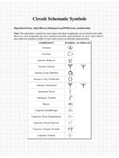
Circuit Schematic Symbols
mercury.pr.erau.eduFerrite Bead Fuse Galvanometer Ground, Chassis Ground, Earth Handset Headphone, Double Headphone, Single Inductor, Air-Core Inductor, Bifilar Inductor, Iron-Core Inductor, Tapped Inductor, Variable Integrated Circuit Inverter Jack, Coaxial . Jack, Phone, 2-Conductor