Example: air traffic controller
AVR Microcontroller Hardware Design Considerations
Ferrite Bead Another decoupling alternative is to connect the device power and ground pins directly to the planes and connect the decoupling capacitor(s) to the planes as close as possible to the power and ground pins. For large packages, placing decoupling capacitors on the opposite side of the board may be the best way of
Tags:
Information
Domain:
Source:
Link to this page:
Documents from same domain

Low Quiescent Current LDO - Microchip Technology
ww1.microchip.com2005-2016 Microchip Technology Inc. DS20001826D-page 1 MCP1700 Features: • 1.6 µA Typical Quiescent Current • Input Operating Voltage Range: 2.3V to 6.0V

MTCH6102 Low-Power Projected Capacitive Touch …
ww1.microchip.com2014 Microchip Technology Inc. DS40001750A-page 1 Description: Microchip’s MTCH6102 is a turnkey projected capacitive touch controller that simplifies adding

Power Factor Correction in Power Conversion …
ww1.microchip.com© 2007 Microchip Technology Inc. DS01106A-page 2 AN1106 FIGURE 1: CURRENT WAVEFORMS WITH AND WITHOUT PFC These waveforms illustrate that …

2.7V to 5.5V Single Supply CMOS Op Amp
ww1.microchip.comMCP601/1R/2/3/4 DS21314G-page 2 © 2007 Microchip Technology Inc. 1.0 ELECTRICAL CHARACTERISTICS Absolute Maximum Ratings † VDD –VSS.....7.0V

Data Encryption Routines for PIC24 and dsPIC Device
ww1.microchip.com© 2006 Microchip Technology Inc. DS01044A-page 1 AN1044 INTRODUCTION Currently, there are three data encryption standards approved …

MCP6021/1R/2/3/4 - Rail-to-Rail Input/Output, 10 …
ww1.microchip.com2001-2017 Microchip Technology Inc. DS20001685E-page 1 MCP6021/1R/2/3/4 Features • Rail-to-Rail Input/Output • Wide Bandwidth: 10 MHz (typical)

MCP1703 250 mA, 16V, Low Quiescent Current
ww1.microchip.com2010 Microchip Technology Inc. DS22049E-page 1 MCP1703 Features: • 2.0 µA Typical Quiescent Current • Input Operating Voltage Range: 2.7V to16.0V

PIC32 GUI Development Board with Projected …
ww1.microchip.comPIC32 GUI Development Board with Projected Capacitance (PCAP) Touch Information Sheet Microchip Technology Inc.

RN4020 Bluetooth Low Energy Module User’s Guide
ww1.microchip.comRN4020 BLUETOOTH LOW ENERGY MODULE USER’S GUIDE 2014 Microchip Technology Inc. DS70005191B-page 7 Preface INTRODUCTION This chapter contains general information that will be useful to know before using the

Using SAM-BA for Linux on SAMA5D3 Xplained
ww1.microchip.comAN-8995 – Using SAM-BA for Linux on SAMA5D3 Xplained: 42328A−06/2014 Page 5 of 19 2. Setup With Ubuntu distributions, a user has to be member of the dialout group to access serial devices like
Related documents
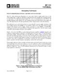
MT-101: Decoupling Techniques - Analog Devices
www.analog.comof the chip as is possible. zThe purpose of this capacitor is to short the high frequency noise away from the chip. All decoupling capacitors should connect to a large area low impedance ground plane through a via or short trace to minimize inductance. Optionally a small ferrite bead in series with the supply pin.

UltraScale Architecture System Monitor User Guide
www.xilinx.comTemperature Sensor, page 28 to differentiate between using an external or on-chip reference. Updated Temperature Sensor, page 40 and Thermal Management, page 91. Updated Figure 2-6, Figure 4-3, and Figure 4-4. 09/19/2014 1.2 Updated first sentence in SYSMON Overview. Updated placement of ferrite bead in Figure 1-3, Figure 3-19, and Figure 5-1.

EMI Design Guidelines for USB Components
www.ti.comwith ferrite beads. Separate ferrite beads may be used on each VBUS line to each downstream USB connector. Each ferrite bead on the VCC lines should be rated at 500 ma. Separate ferrites are useful, not only for EMI suppression, but also for their series DC resistance which limits the inrush current during a hot plug event.
AN0046: USB Hardware Design Guidelines
www.silabs.com• Use a ferrite bead for VBUS. Place near receptacle. • Use a switch that can shut off VBUS if current exceeds 500 mA. • Provide at least 96 uF decoupling capacitance on VBUS. Place near USB receptacle. • Terminate D+ and D- with 15 ohm serial resistors. Place near EFM32. • Use an ESD protection device. Place near USB receptacle.

AN4488 Application note - STMicroelectronics
www.st.com–VDDA can be connected to VDD through a ferrite bead. V e h –T REF+ pin can be connected to VDDA through a resistor. • For the voltage regulator configuration, there is specific BYPASS_REG pin (not available on all packages) that should be connected either to V SS or VDD to activate or deactivate the voltage regulator specific.
PCB Design Guidelines For Reduced EMI - TI.com
www.ti.comEvery edge transition that is sent from the microcomputer to another chip is a current pulse. The current pulse goes to the receiving device, exits through that device’s ground pin, then returns via the ground traces, to the ground pin of the microcomputer (see Figure 2).