Example: marketing
with HD-Wave Technology Installation Guide
Removed Ferrite bead on AC wires l. Addition of link to the Designer web page l. Updated warning about sealing unused power optimizer input connectors l. Output safe voltage is 1V (±0.1V) l. Addition of mounting bracket type 2 l. Mechanical specifications: Addition of inverter models (10kW and 11.4kW) l
Tags:
Information
Domain:
Source:
Link to this page:
Documents from same domain

3-fase omvormers voor commerciële systemen - …
www.solaredge.com3-fase omvormers voor commerciële systemen SE12.5K - SE27.6K OMVORMERS Speciaal ontworpen om te werken met power optimizers Superieur rendement (98,3%) Klein, de lichtste in zijn soort en eenvoudig te installeren

SolarEdge drahtlose Kommunikation ZigBee-Modul zur ...
www.solaredge.comUS s DUSHLD s /dL s H s :P E s H s USL s EDLD s SL www.solaredge.de HAUSAUTOMATION Drahtlose Lösung zur Hausautomation ZigBee-Modul zur Unterstützung der Hausautomation

Single Phase Inverter with HD-Wave Technology
www.solaredge.comModel Number SE3000H-US SE3800H-US SE5000H-US SE6000H-US SE7600H-US SE10000H-US SE11400H-US ADDITIONAL FEATURES Supported Communication Interfaces RS485, Ethernet, ZigBee (optional), Cellular (optional)

Power Optimizer - SolarEdge
www.solaredge.comsolaredge.com POWER OPTIMIZER Power Optimizer Frame-Mounted P370 / P401 / P404 / P500 Fast mount power optimizers with module-level optimization Specifcally designed to …

Three Phase System Installation Guide - SolarEdge
www.solaredge.comAddition of caution - installation in saline environment Clearance for three phase inverters installed side-by-side, single row of inverters outdoors: 5 cm / 2” PVRSS is enabled by default. Enabling/ disabling PVRSS feature can be done from the inverter LCD menus. Addition of reference to troubleshooting undetected devices application note

Remote Site Troubleshooting - SolarEdge
www.solaredge.comPID effect (potential induced degradation) The module power decreases from + to - of the string Check modules 23 Module voltage. Let’s Practice! Inverter Examples. Inverter Example 1 Underperforming string? 26. Inverter Example 1 Switching the timeframe shows that all modules produce roughly

Installation Guide Communicaton Options
www.solaredge.comCommunication è RS485-X Conf è Device Type è SolarEdge Communication è RS485-X Conf è Protocol è Master Communication è RS485-X Conf è Slave Detect The master should report the correct number of slaves. If it does not, verify the connections and terminations. 3. For the meter, select the following:

Versie 2.1-NL 8/2017
www.solaredge.comlaptop of smartphone/tablet met wifi verbinding. Als de wifi instellingen al ingesteld zijn, dan kunt u terugkeren naar de standaardinstellingen en vervolgens een nieuwe wifi verbinding tot stand brengen. Indien u een nieuwe router heeft of als uw netwerknaam is veranderd, dan dient u de omvormer opnieuw aan te melden bij het wifi netwerk.

Technical Note – SunSpec Logging in SolarEdge Inverters
www.solaredge.comMODBUS over TCP Support MODBUS/TCP uses the Ethernet media in physical layers to carry the MODBUS message handling structure and can support a large number of devices in one network; it is easier to integrate into the Local Area Network (LAN) of a company, so it is the choice of more and more customers.

Monitoring Platform User’s Guide - SolarEdge
www.solaredge.comMonitoring Platform User’s Guide for System Owners Emission Compliance This equipment has been tested and found to comply with the limits applied by the local regulations. These limits are designed to provide reasonable protection against harmful interference in a residential installation. This equipment
Related documents

EMI Design Guidelines for USB Components
www.ti.comwith ferrite beads. Separate ferrite beads may be used on each VBUS line to each downstream USB connector. Each ferrite bead on the VCC lines should be rated at 500 ma. Separate ferrites are useful, not only for EMI suppression, but also for their series DC resistance which limits the inrush current during a hot plug event.
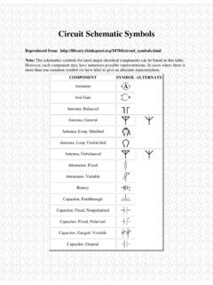
Circuit Schematic Symbols
mercury.pr.erau.eduFerrite Bead Fuse Galvanometer Ground, Chassis Ground, Earth Handset Headphone, Double Headphone, Single Inductor, Air-Core Inductor, Bifilar Inductor, Iron-Core Inductor, Tapped Inductor, Variable Integrated Circuit Inverter Jack, Coaxial . Jack, Phone, 2-Conductor

Understanding and Meeting FPGA Power Requirements White …
www.intel.comrail in the system, a small, cheap filter such as a ferrite bead can be used. In many cases, though, a power converter with sufficiently low output noise is required to deliver a specific, regulated voltage. Traditionally, FPGA board designers have simply used Low Drop-Out linear regulators (LDOs), which
UltraScale Architecture System Monitor User Guide
www.xilinx.com09/19/2014 1.2 Updated first sentence in SYSMON Overview. Updated placement of ferrite bead in Figure 1-3, Figure 3-19, and Figure 5-1. Added Equation 2-7, Equation 2-8, Equation 2-14, Equation 2-15, Equation 2-17, Equation 2-18, Equation 2-20, and Equation 2-21. Removed timing information from Figure 3-3. Updated SYSMON DRP JTAG Write Operation .
ALTERNATIVE 5W STEREO AUDIO AMPLIFIER
www.diodes.comWhen the PAM8406 works without LC filters, it's better to add a ferrite chip bead at the outgoing line of speaker for suppressing the possible . electromagnetic interference. 3. The recommended operating voltage is 5.5V. When the PAM8406 is powered with four battery cells, it should be noted that the voltageof four ...
Understanding How Ferrites Can Prevent and Eliminate RF ...
audiosystemsgroup.comnecting the mic to the input gear was wound around a toroidal ferrite (Fig 1) to form an RF choke that reduces that current. Fig 1 – A toroidal ferrite choke Fig 2 – Ferrites are made in many forms To test the effectiveness of ferrite chokes in audio RFI applications, selected product sam-ples were ordered, and a series of tests were run.