
EE301 - PARALLEL CIRCUITS AND KIRCHHOFF’S CURRENT …
circuits b. Solve for total circuit resistance of a parallel circuit c. State and apply KCL in the analysis of simple parallel circuits d. Demonstrate how to calculate the total parallel resistance given various resistors connected in parallel e. Evaluate why homes, businesses and ships are commonly wired in parallel rather than series. f.
Download EE301 - PARALLEL CIRCUITS AND KIRCHHOFF’S CURRENT …

Information
Domain:
Source:
Link to this page:
Documents from same domain
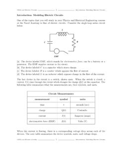
Introduction: ModelingElectricCircuits - usna.edu
www.usna.eduODEs and Electric Circuits 3 Introduction: Modeling Electric Circuits R-L Circuits: If there is no capacitor, we can investigate a flrst order ODE for the current I L dI dt +RI =E
Mathematics & Science - United States Naval …
www.usna.eduMath & Science Core BackgroundMath & Science Core Background ... PCC’s. Navy Professional Core Competencies ManualNavy Professional Core ... Metal Activity Series

SC151 chap 10 learning objectives f17 - USNA
www.usna.eduSC151 - CHAPTER 10 LEARNING OBJECTIVES To satisfy the minimum requirements for this course, you should master the following learning objectives.

TOTAL = 59 - United States Naval Academy
www.usna.edutotal = 59 class of 2022 snapshot applications composition nominating categories presidential..... 790
OPS Ref: (a) OPNAVINST 5530.13C Encl: (1) General ...
www.usna.eduCOMDTMIDNINST 8000.2C 11 Aug 10 Enclosure (1) 2 4. Rifle/Pistol Team Coaches a. Responsible for the safety and security for all weapons and ammunition used and stored in the Bancroft Hall Armory and
GRE PHYSICS STUDY GUIDE - USNA
www.usna.eduGRE PHYSICS STUDY GUIDE by the Department of Physics and Astronomy ... • Study a finite set of physics topics thoroughly, rather than everything in brief • Take a lot of practice tests • Always guess if you are sure you can eliminate at least two answer choices
Perl and CGI (Common Gateway Interface) - USNA
www.usna.edu846 Perl and CGI (Common Gateway Interface) Chapter 25 Applications typically interact with the user through standard input and standard output.
Parents/Family/Friends - USNA
www.usna.eduParents/Family/Friends: This letter contains important information about sending mail and packages to your Midshipman at the US Naval Academy (USNA), and …

ES300 Naval Weapon - USNA
www.usna.eduES300 Naval Weapon Systems Summary: Scientific and engineering principles behind naval weapons systems such as radar, sonar, electro‐optics, communication and guidance systems, explosives and …
Chapter 3 RANDOM VARIATE GENERATION - USNA
www.usna.edu3-1 Chapter 3 RANDOM VARIATE GENERATION ... 3-8 RANDOM VARIATE GENERATION Figure 3.6: Generating Gamma Random Variates ... make use of Excel’s NORMDIST function, as shown in Figure 3.8, to find the cumulative probability of the random variable being less than the bin value. These values are in Column G in
Related documents
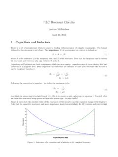
RLC Resonant Circuits - University of Cambridge
mlg.eng.cam.ac.ukTherefore, for series circuits it is in general simpler to calculate the max energy stored by considering the inductor and in parallel circuits by considering the capacitor. Real power is only dissipated in the resistors, P= V Rrms I Rrms = I 2 rms R= V2 Rrms R (16) For the series RLC circuit it is easiest to consider currents, Q(s)! 0 = ! 0 I2 ...
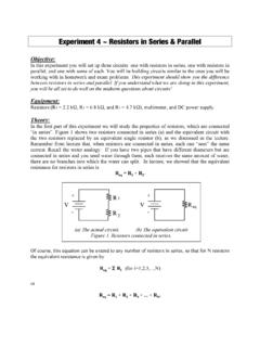
Experiment 4 ~ Resistors in Series & Parallel
www.umsl.eduExperiment 4 ~ Resistors in Series & Parallel Objective: In this experiment you will set up three circuits: one with resistors in series, one with resistors in parallel, and one with some of each. You will be building circuits similar to the ones you will be working with in homework and exam problems. This experiment should show you the difference
Chapter 21: RLC Circuits
www.phys.ufl.eduPHY2054: Chapter 21 19 Power in AC Circuits ÎPower formula ÎRewrite using Îcosφis the “power factor” To maximize power delivered to circuit ⇒make φclose to zero Max power delivered to load happens at resonance E.g., too much inductive reactance (X L) can be cancelled by increasing X C (e.g., circuits with large motors) 2 P ave rms=IR rms ave rms rms rms cos
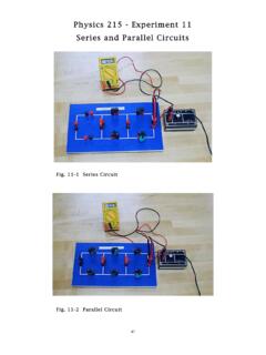
Physics 215 - Experiment 11 Series and Parallel Circuits
www.phy.olemiss.eduSeries and Parallel Circuits 44 + V - 2 The third type of circuit you will construct is a ccombination circuit (Fig. 11-3 and Fig. 11-6). Resistive elements are not connected in series or parallel. To analyze this type of circuit, it should first be simplified (reduced to an equivalent
`Ohm’s Law III -- Resistors in Series and Parallel
www.phys.utk.eduseries resistance. Wires have resistance that depend on wire size, length, and type of material. Wires add series resistance to circuits, just as good and bad connections add also. In order to fully understand electrical circuits and their behavior, one must first understand Ohm’s Law and the principles regarding resistors in series and parallel
Series and Parallel Circuits - Electronics
cie-wc.eduSeries-Parallel Circuits • Series-Parallel circuits can be more complex as in this case: In circuit (a) we have our original complex circuit. In circuit (b) we have resistors R 1 and R 2 combined to get 13.2Ω. R 4 is in series with the newly combined R 12 and their added value is 51.2Ω. And now (c) we are left with R 124 in parallel with R 3.
Circuit A Circuit B
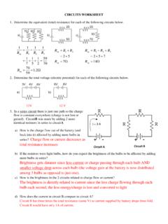
www.livingston.orgCIRCUITS WORKSHEET 1. Determine the equivalent (total) resistance for each of the following circuits below. : 2. Determine the total voltage (electric potential) for each of the following circuits below. 13V 12 V 3. In a series circuit there is just one path so the charge flow is constant everywhere (charge is not lost or gained).
Chapter 8 Natural and Step Responses of RLC Circuits
www.ee.nthu.edu.twSeries . RLC . Circuit. 2 Key points What do the response curves of over-, under-, and critically-damped circuits look like? How to choose R, L, C values to achieve fast switching or to prevent overshooting damage? ...

Series -Parallel Circuits - Oakton Community College
www.oakton.eduOverview of Series-Parallel Circuits A series-parallel circuit, or combination circuit, combines both series and parallel connections. Most electronic circuits fall into this category. Series-parallel circuits are typically used when different voltage and current values are required from the same voltage source. Series components form a series ...

Series and parallel combinations
tuttle.merc.iastate.eduEE 201 series/parallel combinations – 12 Breaking down networks using series and parallel R 3 R 4 R 5 R eq R 2 But not all circuits are simple R 1 combinations of series or parallel resistors. The initial example circuit clearly has some things that are in series and some elements that have a parallel-type connection.