FLOWMETER INSTALLATION INSTRUCTIONS
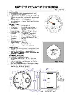
FLOWMETER INSTALLATION INSTRUCTIONS - 1 - Rev 1, 4/25/2005 SAFETY FIRST: Follow ALL safety precautions when working on motor equipment-wear safety glasses! Fuel vapors and liquid are extremely flammable and explosive, personal injury and/or property damage could
Download FLOWMETER INSTALLATION INSTRUCTIONS

Information
Domain:
Source:
Link to this page:
Documents from same domain

NMEA 0183 GPS Receivers - Livorsi Marine
www.livorsi.comHIGHLIGHTS • 1Hz unit outputs NMEA0183 data at 4800 baud, 8 data bits, 1 stop bit, no parity (NMEA 0183 standard). • 10Hz unit outputs same

FUEL LEVEL SENDER - 3 TERMINAL WATER LEVEL …
www.livorsi.comFUEL LEVEL SENDER - 3 TERMINAL WATER LEVEL SENDER - 3 TERMINAL Model # GSFLC All Lengths Model # GSWLC All Lengths Installation Instructions FUEL SENDING UNITS 1. Measure the depth of your tank from the outside top to the tank bottom.

THROTTLES AND CONTROLS - Livorsi Marine
www.livorsi.comTHROTTLES AND CONTROLS Model # TH SERIES (All Configurations) Installation Instructions Thank you for choosing Livorsi Marine® controls. Your new marine engine controls feature a 1 year

VESSELVIEW INSTALLATION INSTRUCTIONS
www.livorsi.comVESSELVIEW INSTALLATION INSTRUCTIONS 90-898278002 MAY 2008 Page 3 / 17 4. Remove the template and insert the VesselView into the panel to ensure fit.
Livorsi DTS Controls Single/Dual Engine Digital …
www.livorsi.comLivorsi DTS Controls- Single/Dual Engine Installation May 2016 Page 6 of 12 . Installing the Control to the Console . 1. Secure the control to the console using 4 x #10 screws and rubber O-Rings.

TEMPERATURE GAUGE and SENDER - Livorsi Marine
www.livorsi.comTemperature Gauge and Senders Trouble Shooting STEP ONE(this usually solves the problem) - Before you do anything else, check for defective wiring or grounds, as …

DIESEL TACHOMETER with SENDER - Livorsi Marine
www.livorsi.comDIESEL TACHOMETER with SENDER Models #GL4000MSGD All Colors ... Mechanical Take-off Rubber Washer Adaptor Sending Coupling Unit 2 of 2 1. Thread adaptor coupling onto sending unit and tighten. 2. Place rubber washer in large end of adaptor coupling. 3. Insert square end of drive tip into sending unit.

Installation and Operation Manual - livorsi.com
www.livorsi.comInstallation and . Operation Manual. ... operation manual provides users with a resource to realize the full potential and capabilities of Vantage View® instrumentation. Covered in this manual are display options, menu navigation and : menu function usage.

Installation and Operation Manual - Livorsi Marine
www.livorsi.comInstallation and Operation Manual ... instructions. FWA Warning Gauge Installation Vantage View® Installation Manual. g Installation Guide ... Installation Guide • Fuel Sender Compatibility Float Arm and Fuel/Water Level Senders are compatible with the Vantage View system. As well as 3

Parameter Range Analog Input LCD Display Name
www.livorsi.com75 Vantage View® Operation Manual ... Engine Oil Temperature 1 175 65262 0-500 ºF Eng Oil Temp Engine Total Hours of Operation 247 65253 0-999999 Hours Engine Hours Engine Speed 190 61444 0-10,000 RPM Engine Speed Engine Exhaust Gas Temperature 173 65270 0-3000 ºF Exh Gas Temp.
Related documents

Chrome - Homepage I2M
i2m.itAll the inputs can be checked using the “Real time inputs view” option in the “Analog and digital inputs” menu. The first screen will show the real time value of the 8 analog inputs, speed 1…

Operating Instructions SCHRIEVER & SCHULZ
schriever-schulz.deOperating instructions T401 – T402 JAQUET LTD status : 2.3.2005 3/18 / 1 Safety instructions

Installation Operation and Maintenance Manual - …
www.greenheck.comDocument 100 VGD100 VariGreen® Drive VariGreen Drive 1 ® Installation Operation and Maintenance Manual Please read and save these instructions for future reference.

SWP B-861 117924 V2 Analog Circle Track …
www.stewartwarnercanada.comB-861 117924 Rev 1: 1/20/05 Installation Instructions Circle Track Tachometer 5” With Peak Recall and Clear 1 PRECAUTIONS: Read ALL instructions …

METEOROLOGICAL INSTRUMENTS - youngusa.com
www.youngusa.commeteorological instruments instructions r.m. young company 2801 aero park drive, traverse city, michigan 49686, usa tel: (231) 946-3980 fax: (231) 946-4772 web: www.youngusa.com pn: 05106-90 rev: n121817

PSN-1 User Manual - innovatemotorsports.com
www.innovatemotorsports.com5 wire is not being used isolate and tape it out of the way. The default analog output configuration is 0V = 7.35 AFR and 5V = 22.39 AFR. 5 The PURPLE wire can be connected to a tach signal to log engine RPM, use the shift light, PowerSafe operation, and window switch.