
HDMI Design Guide 2
utilize the full performance of the device through careful printed circuit board (PCB) design. The paper provides recommendations for-, and explains important concepts of some main aspects of high-speed PCB design. These subjects, presented in the following order, are: layer stack, differential traces,
Download HDMI Design Guide 2

Information
Domain:
Source:
Link to this page:
Documents from same domain

Board Design Guidelines for PCI Express™ Architecture
e2e.ti.comTrace LengthTrace Length §Longer trace length ⇒ loss ↑ ü~0.25 to 0.35 dB inherent loss per inch for FR4 microstrip traces at 1.25GHz §Manage trace lengths to minimize loss üExample: 12” board, 3.5” add-in card lengths Example VNA measurements for differential mstrip trace insertion loss -5.23dB 1.25GHz 20-inch line freq dB Layout ...

The Difference between PMSM & BLDC Motor
e2e.ti.com28 The Difference between PMSM & BLDC Motor • The Torque is a function of current and Back EMF - E bemf – E bemf is a function of how the stator has been wound • PMSM: stator with distributed windings will have a sinusoidal E bemf – In order to achieve constant torque we inject a sinusoidal current • BLDC: stator with concentrated windings will have a trapezoidal E

J-STD-002D Solderability Tests for Component Leads ...
e2e.ti.comSolderability Tests for . Component Leads, Terminations, Lugs, Terminals and Wires . Proposed Standard for Ballot – October 2011 . J-STD-002D – Proposed Standard for Ballot October 2011 2 1 SCOPE . 1.1 Scope This standard prescribes test methods, defect definitions, acceptance criteria, and illustrations for assessing the solderability

PI controller equations - Texas Instruments
e2e.ti.comIn digital power supply control, it finds application in buck, boost, SEPIC, and many other power topologies. ... difference equation with those of practical series and parallel PI implementations. The objective is to find a pair of equations for ... work on non-linear systems led to its introduction, can be derived from a numerical ...

I2C Bus Pull-Up Resistor Calculation
e2e.ti.comI2C Bus Pullup Resistor Calculation Application Report SLVA689–February 2015 I2C Bus Pullup Resistor Calculation RajanArora ABSTRACT Pullup resistor calculation for I2C interface is a commonly asked question. In this application note we show how to use simple equations for this calculation. Contents

Design Guidelines for RCD Snubber of Flyback Converters
e2e.ti.commode (DCM) with several parasitic components, such as pri-mary and secondary leakage inductors, an output capacitor of MOSFET, and a junction capacitor of a secondary diode. Vin Llk1 id Vds + + iD Vo n:1 L mi Llk2 Cj Coss Vin+nVo iD id Vds resonance between Llk1 and Coss diode reverse recovery current Vin+nVo iD id Vds resonance between Lm and ...

HDMI Compliance Test Specification 1 - Texas Instruments
e2e.ti.comAddition of Test for AVI InfoFrame supporting Extended Colorimetry, Content Type and Selectable YCC Quantization Range (8-31) 1.3c 2008/07/25 Addition of TMDS Signal Generator (4.2.1.9) Addition of overmold value for Type C connector(5-1) Addition of test for Active cable and Converter cable(5-2, through 5-8) Removed Active Cable Test (5-9)
Related documents

PCI Express* Board Design Guidelines
www.linelayout.comdesign guidelines for the PCB traces, vias and AC coupling capacitors, as well as add-in card edge-finger and connector considerations. The intent of the guidelines and examples is to help
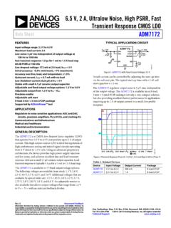
6.5 V, 2 A, Ultralow Noise, High PSRR, Fast Transient ...
www.analog.com6.5 V, 2 A, Ultralow Noise, High PSRR, Fast Transient Response CMOS LDO Data Sheet ADM7172 Rev. D Document Feedback Information furnished by Analog Devices is believed to be accurate and reliable.

Layout Considerations for Pulse Ethernet Magnetics and ...
www.pulseelectronics.comIf a particular tool cannot design differential traces, it is permissible to specify 55 Ω to 65 Ω single-ended traces as long as the spacing between the two traces is minimized. As an example, consider a differential trace pair on Layer I that is 8 mils (0.2 mm) wide and 2 mils (0.05 mm) thick, with a spacing of 8 mils (0.2 mm).
High-Speed Layout Guidelines for Signal Conditioners and ...
www.ti.com3.1 Trace Impedance For high speed signals trace impedance needs to designed as to minimize the reflections in traces. There are two types of trace impedance that need to be taken into consideration when designing high speed signals. Single ended impedance is the trace impedance with reference to ground. Differential Impedance