
Installation and Setup Guide - Lennox
installation uses 18 GAUGE thermostat wire or larger, thermostat wire run length DOES NOT EXCEED 300' (91m), load from any thermostat connection is 1 AMP or LESS. WARNING Improper installation, adjustment, alteration, service or maintenance can cause property damage, personal injury or loss of life. Installation and service must be performed by a
Download Installation and Setup Guide - Lennox

Information
Domain:
Source:
Link to this page:
Documents from same domain

iComfort E30 Homeowner Manual - Lennox
resources.lennox.com3 Features This iComfort® E30 smart thermostat is an electronic, color display touchscreen and 7-day programmable interface which communicates directly with a Smart Hub Controller. After on-line registration is completed, the system may then be

EL296V Gas Furnace Brochure
resources.lennox.comVARIABLE-SPEED BLOWER MOTOR Provides a quiet, consistent flow of air for enhanced comfort, efficiency and humidity control. ICOMFORT®-ENABLED Pairs with the iComfort® S30 ultra smart thermostat, so operation is always in sync with your schedule. A variable-speed motor allows the EL296V to constantly adjust airflow

iComfort S30 Homeowner Manual - Lennox
resources.lennox.comThis iComfort ® S30 ultra smart thermostat is an electronic communicating, color ... 3000 Filter 1 3001 Filter 2 3002 Humidifier Pad 3003 UV Light ... All heat pumps operating in northern climates below 35°F (1.6°C) normally need a supplemental heating source. Usually it is in the form of electric heating
INSTALLATION INSTRUCTIONS - Lennox
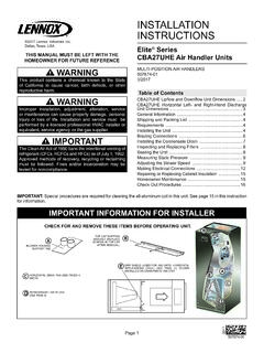
resources.lennox.comThe Clean Air Act of 1990 bans the intentional venting of refrigerant (CFCs, HCFCs and HFCs) as of July 1, 1992. Approved methods of recovery, recycling or reclaiming must be followed. Fines and/or incarceration may be levied for noncompliance. INSTALLATION INSTRUCTIONS MULTI-POSITION AIR HANDLERS 507674-01 3/2017 Elite® Series

INSTALLATION INSTRUCTIONS - Lennox
resources.lennox.comManifold gauge set used with HFC−410A refrigerant systems must be capable of handling the higher system operating pressures. The gauges should be rated for use with pressures of 0 − 800 psig on the high side and a low side of 30" vacuum to 250 psig with dampened speed to 500 psi. Gauge hoses must be rated for use at up to 800

iComfort M30 Smart Thermostat
resources.lennox.comIt also offers enhanced ... • Smooth Setback Recovery starts system early to achieve set point at start of program period. ... Provides temperature control for gas, oil, electric and heat pumps for up to 4 heat / 2 cool multi-stage systems (includes dual-fuel operation).

LENNOX LF25 UNIT HEATERS
resources.lennox.comcomponents produce a durable product that delivers comfort with maximum effi ciency. PATENTED HEAT EXCHANGER A standard feature of all Lennox unit heaters is the tubular heat exchanger, designed to enhance performance and reliability. The patented dimpled tubular design maximizes effi ciency and provides excellent heat transfer by

INSTALLATION INSTRUCTIONS - Lennox
resources.lennox.comSilicone rubber sealant must have a temperature rating of 482°F (250°C), Page 4 i.e., Dow Corning RTV−736 or equivalent. All joints shall be secured with at least two corrosion resistant screws. All accessible joints must be checked for gas tightness after installation

User Guide - Lennox
resources.lennox.comEMERGENCY HEAT allows heat pump system to use a secondary heat source to come on and reach the desired user temperature setting faster. 6. SCHEDULES (1, 2 or 3) See Edit Schedules on page 13 for customizing schedules). 7. ON, AUTO and CIRCULATE - Select by touching the desired fan operation ON, AUTO and CIRCULATE. When selected a
PUREAIR™ AIR PURIFICATION SYSTEM
resources.lennox.comcombines with water vapor in the air to form hydroxyl radicals that destroy a percentage of the remaining odors and chemicals. The PureAir™ air purification system is NOT intended to be used for remediation of active mold growth or high (industrial) levels of chemi-cals in the air. For existing mold growth, the
Related documents

Owner’s Manual - American Honda Motor Company
cdn.powerequipment.honda.comMake sure that any spilled fuel has been wiped up before starting the engine. 31Z376010.book 8 ページ 2013年11月6日 水曜日 午後4時23分
GT 18HP TWiN 44 MO WER GARDEN TRACTOR - Sears Parts …
c.searspartsdirect.comMower Drive Belt Installation Blade.: Sharpening Replacement Brake Adjustment Filter, Air 17 Fuel: Type 12 Storage 26 Fuse 23 G Gauge Wheels 13 H Hood Removal 23 C Carburetor Adjustment Clutch,_ Electric, Adjustment Controls, Tractor Cutting Level, Mower Engine:' Air Screen Oil Change Off Level Oil Type Starting Storage E Lubrication,: Chart 18 ...
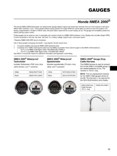
Gauge Sets - American Honda Motor Company
cdn.powerequipment.honda.comCoolant temperature, fuel rate, fuel used, fuel level, trim, battery voltage, engine hours, and vessel speed*. * Requires NMEA 2000 GPS input to backbone. Use of …
A10VO - Robert Bosch GmbH
dc-ca.resource.bosch.com9 Test Equipment: Gauge Test Port Kit 10 10 Port Sizes 11 11 Optional Accessories – Low Oil Shut-Off Block 11 12 Unit Dimensions 12 12.1 A10VO71 12 12.2 A10VO45 14 12.3 A10VO28 16 12.4 A10VO71, 45, 28 18 12.5 A10VO45 Series 50 19 13 Standard Models Used 20 14 Standard Spare Parts 20 14.1 Replacement Pump Control Valve 20

IMPORTANT SAFETY INSTRUCTIONS - Battery Tender
www.batterytender.comto carburetor, fuel lines, or sheet-metal body parts. Connect to a heavy gage metal part of the frame or engine block. g) When disconnecting charger, turn switches to off, disconnect AC cord, remove clip from vehicle chassis, and then remove clip from battery terminal. h) See operating instructions for length of charge information.

1957 Chevy Installation Manual Revision 010615
www.classicinstruments.comJun 15, 2001 · gauge. Fuel Gauge Wiring Diagram Ground +12VDC switched Dash Light Power O G L S I Signal Wire Fuel Level Sender Ground Pulse Signal Generator [SN16] Wiring Attach the signal generator to the transmission speedometer gear housing (where the speedometer cable originally connected). Do not use excessive force to tighten. These signal generators ...
1967-1968 Camaro - Classic Instruments
www.classicinstruments.comOur installation instructions and procedures should take priority over instructions furnished by any other manufactures of ignition systems, wiring harnesses, gauges, etc. TECHNICAL ASSISTANCE . 1-800-575-0461 . ... The fuel level gauge in your instrument cluster is designed to

HELP?: GENERAL APPLICATION: Installation Instructions ...
www.stewartwarner.comFUEL LEVEL GAUGE WIRING (Figure 4): 1. Disconnect negative (-) battery cable. 2. Using 18-ga. wire, connect the (G) terminal to a clean (rust/paint-free) Figure 4ground. 3. Using 18 gauge wire, connect the (I) terminal to a switched +12V source. 4. Using 18-gauge wire, connect the (S) sender terminal of the gauge to the fuel level sender. 5.