INSTALLATION INSTRUCTIONS - MyRheem.com
INSTALLATION INSTRUCTIONS FOR DOWNFLOW SINGLE STAGE GAS FURNACES WITH CONSTANT TORQUE AIR CIRCULATING BLOWER (-)801T DOWNFLOW SERIES (-)(-)80DSX DOWNFLOW SERIES U.L. and/or C.S.A. recognized fuel gas and CO (carbon monoxide) detectors are rec-ommended in all applications, and their installation should be in accordance …
Download INSTALLATION INSTRUCTIONS - MyRheem.com

Information
Domain:
Source:
Link to this page:
Documents from same domain
Parts List Heat Pump Air Handler - MyRheem.com
pts.myrheem.comPage 2 Page 3 - 4 Serial Number Explaination Page 3 - 4 Exploded View Page 5 - 6 Panels & Sheet Metal Parts Page 7 Blower Motor, Motor Bracket Kit, Capacitor Page 8
USER’S INFORMATION MANUAL - MyRheem.com
pts.myrheem.comuser’s information manual for your combination gas heating/electric cooling air conditioning unit do not destroy. please read carefully and keep in a safe place for future
USER’S INFORMATION MANUAL - MyRheem.com
pts.myrheem.comcarbon monoxide (co) is a colorless, odorless, poisonous gas that can cause severe personal in - jury or death. carbon monoxide can be produced by any fuel-burning device, including but not
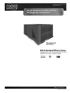
Ruud Commercial Value Series Package Air Conditioner
pts.myrheem.comThe electric furnace comes with fuses for the unit () and for the electric furnace , and is UL certified The electric heating elements are of a wound-wire con-
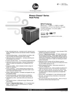
Rheem Classic Series Heat Pump
pts.myrheem.comTable of Contents RP14**A Series 2 TABLE OF CONTENTS ... Internal Pressure Relief Valve √ √ √ √ √ √ √ ... Louver removal for coil cleaning is accomplished by removing one screw and lifting the panel out of the composite base pan ().All RP14**A units utilize single
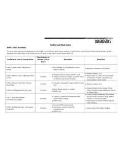
EcoNet and Flash Codes - MyRheem.com
pts.myrheem.comA101_C ECM Blower Motor Communication Failure 4 Flashes Control is unable to communicate with blower motor module RHMV Only Ensure contacts on harness pins/sockets are not, loose corroded or dirty, replace harness or clean pins/sockets Internal fault on motor module, Replace motor module. A105_A ECM Blower Fault - Incomplete
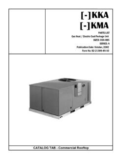
MODEL NUMBER EXPLANATION - MyRheem.com
pts.myrheem.comNot include Limit Baffle or Tube Support Angles. AS-59126-01 AS-59126-03 np LIMIT BAFFLE - Attached to Condenser Bulkhead See Page 13 See Page 13 np TUBE SUPPORT ANGLE - Attached to the Cond. Bulkhead AE-59139-01 AE-59139-01 8 BLOWER BULKHEAD - Does Not Include Tube Support Angle, Blower Extension or Insulation Retainer listed below AS-59130-01 ...
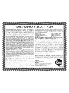
RHEEM LIMITED WARRANTY – PARTS - MyRheem.com
pts.myrheem.comty conditions are not or cease being met),or if the furnace is installed for non-residential use, RHEEM will warrant the primary heat exchanger and the secondary heat exchanger (condensing coil) for a period of Twenty (20) years after the effective date. INDUCED DRAFT MOTOR: 5 Years After the Effective Date - Only for Models:RGPH,RGLH,
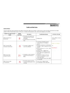
EcoNet and Flash Codes - MyRheem.com
pts.myrheem.comsuction lines, drier, strainers etc. T958_O High Refrigerant Pressure System High pressure switch has opened. Check Refrigerant Charge Check connection of HPS to Drive Yellow 20 Flashes A958_O High Refrigerant Pressure System High pressure switch has opened 3 times and is locked out for one hour

FAULT CODES Normal Operation Limit Control Faults
pts.myrheem.comd3 Airflow Mismatch 61 Blower Fault - Blower Not Running d4 Memor Card Invalid 66 Blower Overspeed Fault d5 Card-Hardware Conflict 68 No Communications with Blower Motor d6 Blower Horsepower Conflict d7 Blower Manufacturer Conflict Gas Valve Faults d8 Old Shared Data 77 No Communications with Gas Valve 78 Gas Valve Servo Fault Flame Sense Signal
Related documents
Gas Piping FactsTANKLESS WATER HEATING
snowcrest.netThe piping must be sized sufficiently enough so that the pressure drop is a half an inch of water column or less, when all the gas appliances are on. This can be the limiting factor when trying to use the existing piping and upgrading from a typical tank-type water heater to a tankless water heater. Typically, the gas piping has to be upgraded to

Models: PLT-5, PLT-12, PLT-20 - Watts
media.wattswater.comImproper installation, adjustment, alteration, service or maintenance can cause property dam-age, serious bodily injury or death. Read instructions completely before proceeding with instal-lation. Only qualified personnel may install or service this equipment in accordance with local codes and ordinances. Do not exceed 80psi (5.5 bar) air charge.

BLUEBOOK - National Grid
www2.nationalgridus.comAND INSTRUCTIONS APPENDIX E . CUSTOMER OWNER GAS PIPING INSPECTION CERTIFICATE APPENDIX F CORRIGATED ATAINLESS STEEL TUBING . APPENDIX G NEW YORK STATE CO ALARM LAW RULE . ... acceptable standards for gas piping and gas appliance installation …

WAS / WYS Series
images.thdstatic.com2. Installation must be performed according to the installation instructions. Improper installation can cause water leakage, undesired performance, electrical shock, or fire. (In North America, installation must be performed in accordance with the requirements of NEC and CEC, by authorized personnel only.) 3.
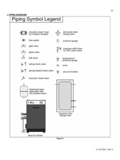
I. PIPING DIAGRAMS
www.htproducts.comEnsure exhaust and intake piping complies with these instructions regarding vent system. Inspect finished combustion air intake and exhaust piping thoroughly to ensure all joints are well secured, airtight, and comply with all applicable code requirements, as well as with the instructions provided in this manual. ...

INSTALLATION AND OPERATING INSTRUCTIONS
www.ibcboiler.com6 INSTALLATION AND OPERATION INSTRUCTIONS HC SERIES BOILERS C -, C -9, C -9, C -, C - The Installer must carefully read this manual to ensure that all installation details can be adhered to. Special attention is to be paid to clearances and access, vent travel and termination, gas supply, condensate removal and combustion air supply.

Installation Instructions - Carrier
www.shareddocs.comFor the indoor unit pipe sizes refer to the indoor unit installation instructions. Table 3 — Piping and Refrigerant NOTE: For piping runs greater than the “Maximum Piping Length with no additional refrigerant charge per System”, see Additional Refri gerant Charge (see Table 5).