LOAD AND RESISTANCE FACTOR DESIGN SPECIFICATION
The AISC Load and Resistance Factor Design (LRFD) Specification for Structural Steel Buildings is based on reliability theory. As have all AISC Specifications, this Specifica-tion has been based upon past successful usage, advances in the state of knowledge, and changes in design practice. This Specification has been developed as a consensus docu-
Download LOAD AND RESISTANCE FACTOR DESIGN SPECIFICATION

Information
Domain:
Source:
Link to this page:
Documents from same domain

56:171 Operations Research Final Examination …
user.engineering.uiowa.eduSolutions 56:171 Operations Research Final Exam '98 page 1 of 14 tststst 56:171 Operations Research tststst stststs Final Examination …
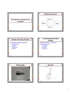
Design InteractionDesign Interaction - University …
user.engineering.uiowa.edu1 © R. Jerz 1 Jan-04 Introduction to Engineering Graphics Introduction to Engineering Graphics © R. Jerz 2 Design InteractionDesign Interaction …

Design of Beams (Flexural Members) (Part 5 of …
user.engineering.uiowa.edu53:134 Structural Design II Shapes that are built up from plate elements are usually called plate girders; the difference is the height-thickness ratio tw h …
![Corrosion Protection.ppt [Read-Only] - University of Iowa](/cache/preview/1/c/f/9/2/e/d/5/thumb-1cf92ed5cf903dbf2b6cd3a840081a01.jpg)
Corrosion Protection.ppt [Read-Only] - University of Iowa
user.engineering.uiowa.eduBare Steel Corrosion Microscopic anodic and cathodic areas exist on a single piece of steel. As anodic areas corrode, new material of different composition is exposed and thus has a different electrical potential. ... Microsoft PowerPoint - Corrosion Protection.ppt [Read-Only]

Fuzzy Logic Basics.ppt - University of Iowa
user.engineering.uiowa.eduFuzzy Logic • Fuzzy logic attempts to model the way of reasonifthh biing of the human brain. • Almost all human experience can be expressed in

Embedded Programming in C - University of Iowa
user.engineering.uiowa.eduEmbedded Programming in C 55:036 Embedded Systems and Systems Software Plusses and Minuses of High-level languages for Embedded Programming • Plusses – Easier syntax (usually) – Lots of libraries and drivers • Minuses – Loss of efficiency – Loss of direct control at the hardware level

NI USB-6008/6009 User Guide and Specifications
user.engineering.uiowa.eduUSER GUIDE AND SPECIFICATIONS NI USB-6008/6009 Bus-Powered Multifunction DAQ USB Device ... Note For information about non-Windows operating system support, refer to the Getting Started ... Getting Started with DAQ»Taking an NI-DAQmx Measurement in LabVIEW.

Lecture 14: Wires - User page server for CoE
user.engineering.uiowa.edu14: Wires CMOS VLSI Design 4th Ed. 22 Crosstalk Delay Assume layers above and below on average are quiet – Second terminal of capacitor can be ignored – Model as C gnd = C top + C bot Effective C adj depends on behavior of neighbors

4 - Aquifers - University of Iowa
user.engineering.uiowa.eduThe aquifer underlies an area of 300 sq. miles and has a saturated thickness of 20 ft. Estimate how much water is in the aquifer in gallons and cubic ft. What is the total amount

Inviscid flow: Euler’s equations of motion
user.engineering.uiowa.eduFlow around a Circular Cylinder A doublet combined with a uniform flow can be used to represent flow around a circular cylinder. The flow around a circular cylinder Velocity potential: cos cos K Ur r θ φθ=+
Related documents
AASHTO LRFD BridgeAASHTO LRFD Bridge Design …
www.concretepipe.orgLoad Factor or Presence Factor?Load Factor or Presence Factor? Standard SpecificationStandard Specification Load Factor is 1.3 x 1.67 = 2.17 Ulti t L d O L WUltimate Load One Lane =W L x 2172.17 Ultimate Load Two Lanes = W L x 2.17 LRFD Specification Load Factor is 1.75 Ultimate Load One Lane = W L x x (1.2 (1.2 x x 1751.75 = 21)2.1)

Design of Compression Members (Part 4 of AISC/LRFD)
user.engineering.uiowa.edu(Part 4 of AISC/LRFD) Euler Buckling of Columns Global buckling of a member happens when the member in compression becomes unstable due to its slenderness and load. Buckling can be elastic (longer thin members) or inelastic (shorter members). Here we shall derive the Euler buckling (critical) load for an elastic column.

Load and Resistance Factor Design - AISC
www.aisc.orgThe fundamental difference between LRFD and the allowable stress design method is, then, that the latter employs one factor (i.e., the Factor of Safety), while the former uses one factor with the resistance and one factor each for the different load effect types. LRFD, by employing more factors, recognizes the fact that, for ex-

TABLE OF CONTENTS - New Millennium Building Systems
www.newmill.comlrfd tables load girder lrfd weight tables joist asd load tables girder asd weight tables sji standard specifications sji code of stand. practice fire resist. ratings osha safety standards deck design guide 001_168 3/28/07 10:52 am page 1

Structural Steel Connections, Joints Details
www.nrc.govLRFD ‐Fasteners • R Q general – where = resistance factor (strength reduction factor) – = nominal resistance (strength) n i i Rn – = overload factors (LRFD‐A4.1) – = loads (such as dead load, live load, wind load, earthquake load) of load …

Design of Bolts in Shear-Bearing Connections per AISC LRFD ...
www.pdhonline.coma) The minimum factored load to be used in designing a connection is 10 kips, except for lacing, sag rods, or girts (LRFD Section J1.7). b) Load sharing for new work is not permitted in bearing-type connections between high strength or A307 bolts and welds in the connection (LRFD J1.9).

ENGINEERING AND DESIGN - United States Army
www.publications.usace.army.milLoad and Resistance Factor Design (LRFD). This guidance is not intended for use in designing repairs to existing HSS. Allowable Stress Design (ASD) guidance is provided for those structure types where LRFD criteria have yet to be developed. 2. Applicability. This manual applies to HQUSACE elements, major subordinate commands,

Chapter 8 Foundation Design - Washington State …
www.wsdot.wa.govIn general, the load and resistance factor design approach (LRFD) as prescribed in the AASHTO LRFD Bridge Design Specifications shall be used, unless a LRFD design methodology is not available for the specific foundation type being considered (e.g., micro-piles). Structural design