SysML Modelling Language explained - Systems Modeling …
SysML Modelling Language explained Page 4 SysML defines the following diagrams: Structure diagrams o The Block Definition Diagram (BDD), replacing the UML2 class diagram o The Internal Block Diagram (IBD), replacing the UML2 composite structure diagram o The Parametric Diagram, a SysML extension to analyse critical system parameters o The Package Diagram remains unchanged
Download SysML Modelling Language explained - Systems Modeling …

Information
Domain:
Source:
Link to this page:
Documents from same domain
Applying Model Based Systems Engineering (MBSE) …
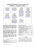
www.omgsysml.org978-1-4577-0557-1/12/$26.00 ©2012 IEEE 1 Applying Model Based Systems Engineering (MBSE) to a Standard CubeSat Sara C Spangelo University of Michigan

Survey of Model-Based Systems Engineering …
www.omgsysml.orgINCOSE MBSE Focus Group Survey of Candidate Model-Based Engineering (MBSE) Methodologies Page 3 of 47 Rev. A May 25, 2007 INCOSE MBSE Focus Group

Survey of Model-Based Systems Engineering …
www.omgsysml.orgINCOSE MBSE Initiative Survey of Candidate Model-Based Engineering (MBSE) Methodologies Page 3 of 70 Rev. B May 23, 2008 INCOSE MBSE Initiative

OMG Systems Modeling Language (OMG SysML™) …
www.omgsysml.org11 July 2006 Copyright © 2006 by Object Management Group. 10 Modeling at Multiple Levels of the System <TITLE>System Design<TITLE> <META http-equiv="REFRESH"

Systems Modeling Language (SysML) Tutorial
www.omgsysml.org• Shared understanding of system requirements and design – Validation of requirements – Common basis for analysis and design – Facilitates identification of risks

Systems Modeling Language (SysML) Tutorial
www.omgsysml.orgWhat is SysML? • A graphical modelling language in response to the UML for Systems Engineering RFP developed by the OMG, INCOSE, and AP233 – a UML Profile that represents a subset of UML 2 with

ISO-15288, OOSEM and Model-Based Submarine …
www.omgsysml.orgISO-15288, OOSEM and Model-Based Submarine Design Paul Pearce1 and Matthew Hause2 1Senior Systems Engineer Deep Blue Tech Pty Ltd, Osborne, SA 5017, Australia Email: Paul.Pearce@deepbluetech.com.au
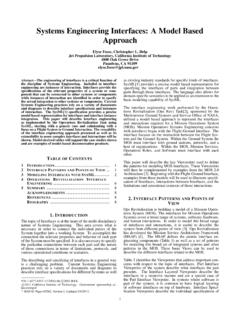
Systems Engineering Interfaces: A Model Based …
www.omgsysml.orgSystems Engineering Interfaces: A Model Based Approach Elyse Fosse, Christopher L. Delp Jet Propulsion Laboratory, California Institute of Technology

An Ontology for State Analysis: Formalizing the Mapping to ...
www.omgsysml.orgAn Ontology for State Analysis: Formalizing the Mapping to SysML David A. Wagner Jet Propulsion Laboratory 4800 Oak Grove Dr. Pasadena, CA 91109 818-354-1148 David.A.Wagner@jpl.nasa.gov Nicolas Rouquette Jet Propulsion Laboratory 4800 Oak Grove Dr. Pasadena, CA 91109 818-354-9600

A Practical Approach for Modelling Submarine Subsystem ...
www.omgsysml.org347 Submarine Institute of Australia Science, Technology & Engineering Conference 2013 PAPER 12 A Practical Approach For Modelling Submarine Subsystem Architecture In SysML Paul Pearce
Related documents
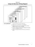
Section 2 Using the Electrical Wiring Diagram
www.autoshop101.comUsing the Electrical Wiring Diagram Body Electrical Diagnosis - Course L652 3 One of the keys to a quick and successful electrical diagnosis is correctly

Reliability Block Diagram (RBD)
reliabilityeducation.comCopyright 2007, ITEM Software, Inc. Page 3 of 6 parallel, the system fails if one fails short. The reliability block diagram for such a system for the "fail

Differential current outputs: 2 mA to 20 mA FUNCTIONAL ...
www.analog.com14-Bit, 210 MSPS TxDAC® D/A Converter Data Sheet AD9744 Rev. C Document Feedback Information furnished by Analog Devices is believed to be accurate and reliable.

LIST OF FIGURES - mit.edu
www.mit.edu17 LIST OF FIGURES Figure 1.1 Thesis research process . . . . . . . . . . . . . . . . . . . . . . . . . 32 Figure 1.2 Discontinuity in complexity, risk, and cost at ...

Appendix A Toyota Wiring Diagram Symbols
www.autoshop101.comAppendix A A-2 TOYOTA Technical Training IGNITION SWITCH A key operated switch with several positions which allow various circuits to become operational, including the primary ignition circuit.

MOMENT CURVATURE ANALYSIS - structsource.com
structsource.com• Moment curvature analysis is a method to accurately determine the load-deformation behavior of a concrete section using nonlinear material stress-strain relationships.

HILUX Electrical Wiring Diagram - Tuning Concepts
www.tuningconcepts.comNOTICE When handling supplemental restraint system components (removal, installation or inspection, etc.), always follow the direction given in the repair

Block 16/20 – County Fair - patsloan.typepad.com
patsloan.typepad.comSQUARE Block to 13.5” x 13.5” Finished in the quilt is Size 13” Block 16/20 – County Fair Enter your email for my notice of each new block release & join my online group to share with everyone!

SONJA'S WINDOWS - Quilts from the Heart
www.quiltsfromtheheart.org3 Refening to Diagram Ill, cut sewn squares in half twice diagonally. Press units open carefully. Each sewn square makes 4 pieced units, for 20 total. MRke 20 total Diagram* P Sew tan g1/2- Strips to top and bottom of pieced unit, easing unit edge to fit, if necessary.