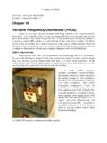
Variable Frequency Oscillators (VFOs)
5. Chapter 10, Harris ohm load. In Chapter 6 you were introduced to Chebyshev filters designed for 50 ohms. However, here we have no need for power, just voltage. Therefore, the filter is designed for 500 ohms, which is plenty of power for this application. Values are given for both a 80 meter VFO (3.5 to 4.0 MHz) or a 5 MHz VFO (5.0 to 5.5 MHz).
Download Variable Frequency Oscillators (VFOs)

Information
Domain:
Source:
Link to this page:
Documents from same domain
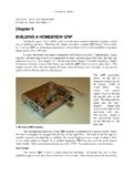
Chapter 6 BUILDING A HOMEBREW QRP - QRP ARCI
www.qrparci.org2. Chapter 6, Harris Unfortunately crystal control means you must order $18 custom crystals for your favorite frequencies in each band.
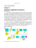
Chapter 13 BUILDING A HOMEBREW HF RECEIVER
www.qrparci.org5. Chapter 13, Harris Homebuilt all-band dual conversion HF ham receiver. Start with a single band, single conversion superhetrodyne My "adequate receiver" is shown above.
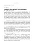
HOME-BUILDING AMATEUR RADIO EQUIPMENT
www.qrparci.org3. Chapter 2, Harris vehicle, you don’t even need a power supply, you just run it directly off the battery using the cigarette lighter outlet.
Chapter 14 VACUUM TUBE RECEIVERS AND …
www.qrparci.org4. Chapter 14, Harris described here needs at least 250 volts to deliver 5 watts output. And because of its low energy conversion inefficiency, plan on supplying 15 watts DC power instead of just 5 watts.
Chapter 12 SIMPLIFIED QRO AMPLIFIER DESIGNS
www.qrparci.org4. Chapter 12, Harris RF input drive, the transistors immediately ran away and drew huge currents. Gee, something must be wrong with the bias circuit!
CRYSTAL SETS TO SIDEBAND - QRP Amateur Radio Club ...
www.qrparci.org1. Chapter 1, Harris CRYSTAL SETS TO SIDEBAND A guide to building your own amateur radio station By Frank W. Harris, KØIYE 3850 Pinon Drive
CHAPTER 5 GETTING ON THE AIR - QRP ARCI
www.qrparci.org3. Chapter 5, Harris certain kinds of integrated circuit. My rules have taught me how the circuits work. I’ve learned plenty. And by golly, when
Related documents
10. Reduce Losses in the Transmission and Distribution …
www.4cleanair.orgAug 10, 2014 · reduce total power consumption (see Chapter 5). Because they are transformers, they involve both core losses and resistive losses, and attention to both the materials and the sizing of these affects the level of line losses. Primary Distribution Lines. Primary lines connect substations to circuits that bring power into business

ELECTRONICS and CIRCUIT ANALYSIS using MATLAB
ee.hacettepe.edu.trCHAPTER SIX AC ANALYSIS AND NETWORK FUNCTIONS 6.1 STEADY STATE AC POWER 6.1.1 MATLAB functions quad and quad8 6.2 SINGLE- AND THREE-PHASE AC CIRCUITS 6.3 NETWORK CHARACTERISTICS 6.3.1 MATLAB functions roots, residue and polyval 6.4 FREQUENCY RESPONSE 6.4.1 MATLAB Function freqs SELECTED BIBLIOGRAPHY EXERCISES
Op Amps for Everyone Design Guide (Rev. B)
web.mit.eduthe designer to bias circuits when the inputs are referenced to ground, and Chapter 4 ... can’t exist without feedback, and feedback has inherent stability problems, so feedback and stability are covered in Chapter 5. Chapters 6 and 7 develop the voltage ... 14 where the reader is shown how design the converter to transducer/actuator interface

SPICE-Simulation using LTspice IV
ieca-inc.comProject 6: OPA Circuits 62 10.1. Starting with an Inverting Amplifier 62 ... The Flyback Converter 73 11.4. The Step Down Converter 75 12. ... Second Example: Dirac Test of a 110MHz Lowpass Filter (see Chapter 14.2) 142 20.2.1. Simulating S21 (= Forward Transmission) 142 20.2.2. Simulation of S11 (= input reflection) or S22 (= output reflection ...

Introduction to Digital Data Transmission
www.eg.bucknell.edusample to a binary number (i.e., an analog-to-digital converter). Each sample value is therefore represented by a sequence of 1s and 0s, and the communication system associ-ates the message 1 with a transmitted signal s1 (t) and the message 0 with a transmitted signal s0(t). During each signaling interval either the message 0 or 1 is ...

ABB drives Reference manual Grounding and cabling of drive ...
library.e.abb.comContents of this chapter This chapter gives a description of the manual. Applicability This manual is applicable for low voltage AC and DC drive systems. The drive system in this manual consists of the supply transformer, input power cable of the drive, the variable speed drive (frequency converter), motor cable and motor. Target audience

EN / FEN-31 HTL Encoder Interface User's Manual - ABB
library.e.abb.comThis chapter states the general safety instructions that must be ... minutes to discharge before working on the frequency converter, the motor or the motor cable. It is good practice to check (with a ... control circuits even when the drive mains power is shut off.

CHAPTER 10: PASSIVE COMPONENTS - Analog Devices
www.analog.comCHAPTER 10: PASSIVE COMPONENTS Introduction When designing precision analog circuits, it is critical that users avoid the pitfall of poor passive component choice. In fact, the wrong passive component can derail even the best op amp or data converter application. This section includes discussion of some basic traps of choosing passive components.
CHAPTER 3: SENSORS - Analog Devices
www.analog.comchapter 3: sensors section 3.1: positional sensors 3.1 linear variable differential transformers (lvdt) 3.1 hall effect magnetic sensors 3.6 resolvers and synchros 3.9 inductosyns 3.13 accelerometers 3.15 imems® angular-rate-sensing gyroscope 3.19 gyroscope description 3.19 coriolis accelerometers 3.20 motion in 2 dimensions 3.21
Chapter 14 Review of Quantization - Chester F. Carlson ...
www.cis.rit.eduhold circuits. The simplest quantizer converts an analog input voltage to a 1-bit digital output and can be constructed from an ideal di fferential amplifier, where the output voltage Voutis proportional to the difference of two voltages Vinand Vref: Vout= α(Vin−Vref) Vref is a reference voltage provided by a known source. If αis large ...