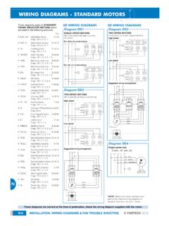
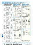
WIRING DIAGRAMS - STANDARD MOTORS
controller (S/C) is not required 1Ø WIRING DIAGRAM Diagram ER4 1Ø WIRING DIAGRAMS M 1~ LNE 3 active wires plus auto-reset thermal contacts Codes: CE19.. to CE28.. + other fans as shown Brown Black Blue M 1~ Green/Y ellow Brown Cap Black CE31 only Single phase AC motor with capacitor Blue or Grey A N
Download WIRING DIAGRAMS - STANDARD MOTORS
Information
Domain:
Source:
Link to this page:
Documents from same domain
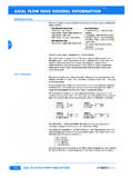
AXIAL FLOW FANS GENERAL INFORMATION - …
www.fantech.com.auc axial flow fans general information
WIRING DIAGRAMS - STANDARD MOTORS - …
www.fantech.com.au© fantech 2008 installation, maintenance & wiring diagrams m-7 wiring diagrams - standard motors m 3Ø wiring diagrams 1Ø wiring diagrams …
WIRING DIAGRAMS - STANDARD MOTORS - fantech.com.au
www.fantech.com.au© fantech 2008 installation, maintenance & wiring diagrams m-7 wiring diagrams - standard motors m 3Ø wiring diagrams 1Ø wiring diagrams m 3~ m 3~ high speed delta ...
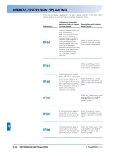
INGRESS PROTECTION (IP) RATING - Fantech
www.fantech.com.auINGRESS PROTECTION (IP) RATING ... First Numeral Protection against contact and ingress of foreign bodies Second NumeralProtection against water. IP44 Protection against contact with live or moving parts inside the enclosure by tools, wires, or …
AXIAL FLOW FANS GENERAL INFORMATION - Fantech
www.fantech.com.auFlameproof or increased-safety motors are wired to the outside of the case and left with a generous length of lead. This is so the client can connect to their own terminal box in accordance with the requirements for the particular hazardous zone. AXIAL FLOW FAN RANGE DUCT MOUNTED Direct-drive - AP Series (315 to 2000 mm diameter)
CENTRIFUGAL FANS; SWSI & DWDI - Fantech
www.fantech.com.auThe Centrifugal Fan range of backward-inclined laminar or aerofoil-section fans, encompasses both single-width and double-width units. They feature high strength fully welded mild steel casings and each range is available in 20 sizes, extending from 305mm (12 inch) to …
Fan Laws - Fans | Exhaust Fans | Ventilation Fans
www.fantech.com.auqv = volume flow of air, m3/sec n = rotational speed of fan d = diameter of fan p = pressure developed by the fan ρ = density of air, kg/m3 PR = power absorbed by the fan, kW B = barometric pressure (millibars) T = absolute temperature, K (K = °C + 273) ptF = fan total pressure, Pa psF = fan static pressure, Pa pdF = fan dynamic/velocity ...
Related documents
Trailer Wiring Diagrams | etrailer
www.actionoutboards.comTrailer Wiring Diagrams Trailer Wiring Connectors Various connectors are available from four to seven pins that allow for the transfer of power for the lighting as well as auxiliary functions such as an electric trailer brake controller, backup lights, or a …
LC-2 Digital Air/Fuel Ratio (Lambda) Sensor Controller Manual
www.innovatemotorsports.com2 Mounting and Wiring the LC-2 2.1 Mounting The LC-2 controller body should be mounted inside the cabin or in another dry, protected location away from the elements. Physically mount the unit away from all ignition or stereo components …

TROUBLESHOOTING COMMON Make sure that the SmartPort …
www.hunterindustries.comSTEP 3: Check Sensor and Sensor Wiring Remove one sensor wire from one of the SEN terminals. If the controller displays SEN OFF, a problem exists with the sensor and/or sensor wiring. Common problems with sensor wiring include: 1) staples through wire insulation, 2) poor wire splices, 3) metal contacting sensor wires through cut in the insulation.
Variable Air Volume (VAV) Controller Technical Bulletin
cgproducts.johnsoncontrols.com2 VAV Controller—Variable Air Volume (VAV) Controller Wiring Details Page 25 • Power Source and Loads 26 • Grounding and Isolation 27 • I/O and Communication Terminals 29 • Power, Zone Bus, and N2 Connections 36 • Analog Inputs 36 • Binary Inputs 38 • Binary Outputs 38 • Analog Outputs 38 • Zone Bus 39 • Wiring to RLY50/002 Relays 39

JADE Economizer Module
customer.honeywell.comFor S-BUS wiring, the sensors may be mounted up to 200 ft. (61 m) from the JADE controller. When the length of wire is over 100 feet use twisted pair shielded wire. NOTE: All wiring is polarity insensitive. Refer to Fig. 1 through Fig. 7 for common wiring configurations. Refer to Fig. 8 for use with the Smart VFD.
Wiring Diagrams - Kohler Power
www.kohlerpower.com4 Wiring Diagrams TP-6712 4/10 Wiring Diagrams Use the Wiring Diagram Cross-Reference chart to determine the wiring diagram version number for a given model number and spec number. Then find that version number, the controller type, and the alternator type on the Wiring Diagrams Reference chart to determine the wiring diagram numbers for your unit.

Product Bulletin DVC6200 Digital Valve Controller ...
www.emerson.comController The FIELDVUE DVC6200 digital valve controller is a HART® communicating instrument that converts a two‐wire 4‐20 mA control signal into a pneumatic output to an actuator. It can easily be retrofitted in place of existing analog positioners on most Fisher and non‐Fisher pneumatic actuators. Features Reliability

Dimensions WBL RELAYS/WIRING INPUT CARDS ANALOG …
www.walchem.comRELAYS/WIRING INPUT CARDS ANALOG OUTPUTS ETHERNET WBL BOILER SENSORS WCT COOLING TOWER SENSORS WPH pH/ORP SENSORS WDS DISINFECTION SENSORS WCN CONDUCTIVITY SENSORS RELAYS/WIRING INPUT CARDS ANALOG OUTPUTS ETHERNET-SENSORS WCT600P CS N E - BI Example: WCT600PCSNE- BI KEY …

Installation Instructions - Painless Wiring
www.painlessperformance.comThe PERFECT TORC Transmission Controller supports 1993 to present 4L80E transmissions. However, the 1993 and earlier 4L80E transmissions use a different internal wiring harness and main pass through connector. These early designs inherently leak fluid through their pass through connector. General Motors has several Technical
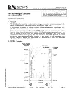
3. EP1502 Wiring and Setup
www.security.us.panasonic.comCommunication Wiring: The EP1502 controller communicates to the host via the on-board 10-BaseT/100Base-TX Ethernet interface (port 0) and/or RS-232 interface (port 1). RS-232 interface is for direct one to one connection to a host computer port or via modem, 25 feet maximum. The serial I/O device communication port (TB3) is a 2-wire RS-485 ...