Zero Voltage Switching - Texas Instruments
Zero Voltage Switching Resonant Power Conversion Bill Andreycak ing zero current, hence zero power switching. And while true, two obvious concerns can in1pede the quest for high efficiency operation with high voltage inputs. By nature of the resonant tank and zero current switching limitation, the peak switch
Download Zero Voltage Switching - Texas Instruments

Information
Domain:
Source:
Link to this page:
Documents from same domain

LM136-2.5,LM236-2.5,LM336-2 - TI.com
www.ti.comLM136-2.5/LM236-2.5/LM336-2.5V Reference Diode General Description The LM136-2.5/LM236-2.5 and LM336-2.5 integrated cir-cuits are …

SimpleLink™ CC3120, CC3220 Wi-Fi ... - Texas …
www.ti.comUser User x x x x x x x x x x x x x x x x x x x x Application Servers Vendor IoT Devices Internet Introduction www.ti.com 4 SWRA509A–February 2017–Revised March 2017 Submit Documentation Feedback

www.ti.com SNVS749F - Texas Instruments
www.ti.comLM136-2.5-N SNVS749F – MAY 1998– REVISED APRIL 2013 www.ti.com Typical Performance Characteristics (continued) Temperature Drift Figure 13. …

MSP430x2xx Family User's Guide (Rev. J) - TI.com
www.ti.comMSP430x2xx Family User's Guide Literature Number: SLAU144J December 2004– Revised July 2013

1.8-V Micropower CMOS Operational Amplifier …
www.ti.com5 OPA2333-HT www.ti.com SBOS483I –JULY 2009–REVISED MAY 2015 Product Folder Links: OPA2333-HT Copyright © 2009–2015, Texas Instruments Incorporated Submit Documentation Feedback

LMC6482 CMOS Dual Rail-To-Rail Input and Output ...
www.ti.comLMC6482 www.ti.com SNOS674E –NOVEMBER 1997–REVISED APRIL 2015 5 Pin Configuration and Functions D, DGK and P Packages 8-Pin SOIC, VSSOP and PDIP (Top View) Pin Functions PIN TYPE DESCRIPTION NO.

OPAx354 250-MHz, Rail-to-Rail I/O, CMOS …
www.ti.comOPA354 IN +IN V OUT V+ V Product Folder Order Now Technical Documents Tools & Software Support & Community Reference Design An IMPORTANT NOTICE at the end of this data sheet addresses availability, warranty, changes, use …

Analog linearization of resistance temperature …
www.ti.com21 Analog Applications Journal Texas Instruments Incorporated 4Q 2011 www.ti.com/aaj High-Performance Analog Products …

TMS320C28x DSP/BIOS 5.x Application …
www.ti.comSPRU625L—August 2012 API Functional Overview 9 Submit Documentation Feedback www.ti.com Naming Conventions 1.2 Naming Conventions The format for a DSP/BIOS operation name is a 3- or 4-letter prefix for the module that contains the

WL18x7MOD WiLink™ 8 Dual-Band Industrial …
www.ti.comProduct Folder Order Now Technical Documents Tools & Software Support & Community Reference Design An IMPORTANT NOTICE at the end of this data sheet addresses availability, warranty, changes, use in safety-critical applications,
Related documents

Power Transformer Factory Test using IEEE Standards
r5.ieee.orgZero phase sequence voltage X Future/System reference Temperature rise X X Thermal and performance List of tests 8 Dielectric tests Routine Design Others Remark Lightning impulse X X Dielectric test Switching impulse X Dielectric test Applied voltage test X Dielectric test Induced voltage with or without
Chapter 9: FET Amplifiers And Switching Circuits
staff-old.najah.eduSwitching Circuits 9-1: The Common Source Amplifier (CS Amplifier) ... A zero-biased common-source amplifier for ... Determine the voltage gain and the input resistance of the amplifier in Figure 9–20. VDD is negative because it is a p-channel device. From data
SECTION 4 SWITCHED CAPACITOR VOLTAGE CONVERTERS …
www.analog.comthe switching cycle. During the second half of the switching cycle, its voltage is inverted and applied to capacitor C2 and the load. The output voltage is the negative of the input voltage, and the average input current is approximately equal to the output current. The switching frequency impacts the size of the external
Switching regulator fundamentals (Rev. C) - Texas …
www.ti.com1. A voltage across an inductor results only from a current that changes with time. A steady (DC) current flowing in an inductor causes no voltage across it (except for the tiny voltage drop across the copper used in the windings). 2. A current flowing in an inductor can not change value instantly (in zero time), as this would require

Physical Explanation - Vishay Intertechnology
www.vishay.comSwitching on Characteristic Forward recovery time, tfr The time required for the voltage to reach a specified value (normally 110 % of the steady state forward voltage drop), after instantaneous switching from zero or a specified reverse voltage to a specified forward biased condition (forward current).
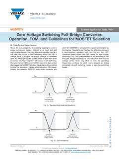
MOSFETs Zero-Voltage Switching Full-Bridge Converter ...
www.vishay.comswitching-related EMI, and eliminates the need for primary-side snubbers. Fig. 2 - Typical ZVSFB Circuit WHY ZERO-VOLTAGE SWITCHING When a MOSFET turns on, there are losses due to voltage and current overlap (Figure 3) and the discharge of stored energy in its Coss capacitor. In ZVS the Coss is tricked into