Transcription of Digital Electronics
1 Digital Electronics 1 E. COATES 2007 -2020 Digital Electronics Digital Logic introduction . Digital logic is the foundation, not only of computing but also many other electronic devices and control systems found in almost every part of modern life. This module introduces the basics of Digital logic and shows how the whole of Digital Electronics depends on just seven types of logic gates, connected together with a minimum of additional components. Combinations of logic gates then form circuits that can perform specific tasks within larger circuits or systems. The process of producing complex circuits using combinations of basic devices is called Combinational Logic.
2 There are many ways that a number of logic gates can be combined to perform a specific task. They may all work, but some combinations will perform the task that better than others. For example, a circuit designer may want to design a combinational logic circuit that uses the minimum number of gates, or performs the required task in the least time, or at the minimum cost. This module also introduces the way Digital logic gates work and teaches you key methods by which a basic Digital logic circuit design may be minimised, made more efficient and/or cheaper. Module 2 What you ll learn in Module 2 Section introduction . Section Logic Gates. 74 Series standard logic gates. Standard logic functions. AND, OR, NAND, NOR, XOR, XNOR, NOT.
3 Truth tables for standard logic functions. Section Combinational Logic Combining logic gates. Truth tables. Boolean equations. Section Boolean Algebra. Simplifying Boolean equations Boolean laws and rules De Morgan s theorem Section karnaugh Maps. Constructing karnaugh maps Minimising karnaugh maps Software for Boolean simplification Section Digital Logic Quiz. Test your knowledge of Digital Logic. Digital Logic Digital Electronics MODULE 2 E. COATES 2007-2020 Logic Gates Seven Basic Logic Gates Digital Electronics relies on the actions of just seven types of logic gates, called AND, OR, NAND (Not AND), NOR (Not OR), XOR (Exclusive OR) XNOR (Exclusive NOR) and NOT.
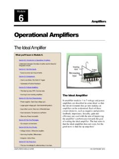
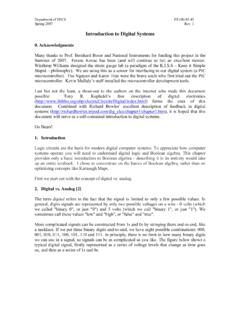
4 Shows each of the seven basic logic gates, which may be illustrated by either the traditional "Distinctive Shape" ANSI symbol or the newer rectangular IEC symbol, and a written description of its logic function compared with its Boolean equation. Because, in binary logic there are only two states, 1 and 0 or on and off, NOT in the world of binary logic therefore means the opposite of . If something is not 1 it must be 0, if it is not on, it must be off. So NAND (not AND) simply means that a NAND gate performs the opposite function to an AND gate. A logic gate is a small transistor circuit, basically a type of amplifier, which is implemented in different forms within an integrated circuit. Each type of gate has one or more (most often two) inputs and one output.
5 The principle of operation is that the circuit operates on just two voltage levels, called logic 0 and logic 1. Traditionally many logic circuits use 5V to represent logic 1 and 0V to represent logic 0 although in many modern circuits 1 and 0 are represented by and 0V. When either of these voltage levels is applied to the inputs, the output of the gate responds by assuming a 1 or a 0 level, depending on the particular logic of the gate. The logic rules for each type of gate can be described in different ways, by a written description of the action, by a truth table, which is a table showing all the possible logic states at the inputs and output of the gate, or by a Boolean algebra statement. What you ll learn in Module After studying this section, you should be able to: Describe the action of logic gates.
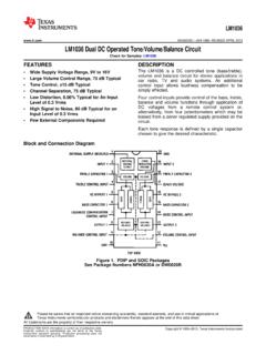
6 AND, OR, NAND, NOR, NOT, XOR and XNOR Using Boolean expressions. Using truth tables. Understand the use of universal gates. NAND NOR Recognise common 74 series ICs containing standard logic gates. Digital Logic Digital Electronics MODULE 3 E. COATES 2007-2020 Boolean Statements Boolean statements use letters from the beginning of the alphabet, such as A, B, C etc. to indicate inputs, and letters from the second half of the alphabet, very commonly X or Y and sometimes Q or P to label an output. The letters have no value meaning in themselves, they are just used to label the various points in the circuit.
7 The letters are then linked by a symbol indicating the logical action of the gate. The symbol indicates AND although in many cases the may be omitted. (A B may also be written as AB or ) + indicates OR indicates XOR (Exclusive OR) Although the symbols and + are the same as those used in normal algebra to indicate product (multiplication) and sum (addition) respectively, in binary logic the + symbol does not exactly correspond to sum. In Digital logic 1 + (OR) 1 = 1, but the binary sum of 1 + (plus) 1 = 102, therefore in Digital logic + must always be considered as OR. Three further types of logic gate give an output that is an inverted version of the three basic gate functions listed above, and these are indicated by a bar drawn above a statement using the AND, OR, or XOR symbols to indicate NAND, NOR and XNOR.
8 A B means A AND B but A B means A NAND B The action of any of the gates can therefore be described by using its Boolean equation. For example: An AND gate gives an output of logic 1 when input A AND input B are at logic 1, but a NAND gate would give a logic 0 output for the same input conditions. Also where the AND gate gives a logic zero for a particular input combination, the NAND gate would give a logic 1. The N in the gate s name, or the bar above the Boolean expression therefore indicates that the output logic is inverted . In Digital logic NAND is NOT AND or the opposite of AND. Similarly NOR is NOT OR and XNOR is NOT XOR. The final gate type, the NOT gate or inverter is a single input gate that has an output having the opposite logic state, or the inverse of the input. Describing the Action of Logic Gates Alternatively the action of any of the 7 types of logic gate can be described using a written description of its logic function.
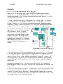
9 The AND gate output is at logic 1 when, & only when all its inputs are at logic 1, otherwise the output is at logic 0. The OR gate output is ate logic 1 when one or more of its inputs are at logic 1. If all its inputs are at logic 1 , the output is at logic 0. The NAND gate output is at logic 0 when & only when all its inputs are at logic 1. Otherwise the output is at logic 0. The NOR gate output is at logic 0 when one or more of its inputs are at logic 1. If all of its inputs are at logic 0, the output is at logic 1. The XOR gate output is at logic 1 when and only one of its inputs is at logic 1. Otherwise the output is at logic 0. Boolean Symbols for Gates Digital Logic Digital Electronics MODULE 4 E.
10 COATES 2007-2020 The XNOR gate output is at logic 0 when one and only one of its inputs is at logic 1 Otherwise the output is at logic 1. (It is therefore similar to the XOR gate, but its output is inverted). The NOT gate output is at logic 0 when its only input is at logic 1, and at logic 1 when its only input is at logic 0. For this reason it is often called an INVERTER. Truth Tables Another useful way to describe the action of a Digital gate (or a whole Digital circuit) is to use a truth table. Each table consists of two or more columns, one column for each input or output; the number of lines in the column will be enough to record all possible logic states for that input or output. illustrates two typical truth tables for circuits of different levels of complexity.