Transcription of EJA430E Gauge Pressure Transmitter - Yokogawa
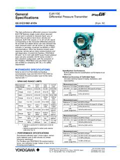
1 GeneralSpecifi cations<<Contents>> <<Index>>EJA430 EGauge Pressure TransmitterYokogawa Electric Corporation2-9-32, Nakacho, Musashino-shi, Tokyo, 180-8750 JapanTel.: 81-422-52-5690 Fax.: 81-422-52-2018GS 01C31E01-01 ENGS 01C31E01-01EN Copyright June 201220th Edition Feb. 2022 The high performance Gauge Pressure Transmitter EJA430E features single crystal silicon resonant sensor and is suitable to measure liquid, gas, or steam Pressure . The EJA430E outputs a 4 to 20 mA DC signal corresponding to the measured Pressure . It also features quick response, remote setup and monitoring via BRAIN or hart communications and self-diagnostics. FOUNDATION Fieldbus, PROFIBUS PA and 1 to 5 V DC with hart (Low Power) protocol types are also series models in their standard confi guration, with the exception of the Fieldbus, PROFIBUS and Low Power types, are certifi ed as complying with SIL 2 for safety requirement.
2 STANDARD SPECIFICATIONSR efer to GS 01C31T02-01EN for Fieldbus communication type and GS 01C31T04-01EN for PROFIBUS PA communication type for the items marked with . SPAN AND RANGE LIMITSM easurementSpan/RangeMPapsi (/D1)bar(/D3)kgf/cm2(/D4)HSpan5 to 500 kPa20 to 2000 to to 5 Range 100 to 500 kPa 400 to 2000 inH2O 1 to 5 1 to to to to 35 Range to to 500 1 to 35 1 to to 16 20 to to to 160 Range to 16 to 2300 1 to 160 1 to 160 PERFORMANCE SPECIFICATIONSZero-based calibrated span, linear output, wetted parts material code S and silicone oil, unless otherwise Fieldbus and PROFIBUS PA communication types, use calibrated range instead of span in the following specifi cation ConformanceEJA-E series ensures specifi cation conformance to at least 3 .Reference Accuracy of Calibrated Span(includes the eff ects of terminal-based linearity, hysteresis, and repeatability)Measurement spanHReferenceaccuracyX span of SpanX > span ( + URL/span)% of SpanX70 kPa (280 inH2O)URL(upper range limit)500 kPa (2000 inH2O)Measurement spanABReferenceaccuracyX span of SpanX > span ( + URL/span)% of MPa (50 psi) MPa (230 psi)URL(upper range limit) MPa (500 psi)16 MPa (2300 psi)[Style: S2]2 All Rights Reserved.
3 Copyright 2012, Yokogawa Electric Corporation<<Contents>> <<Index>>GS 01C31E01-01EN[When /HAC is specified]Measurement spanHReferenceaccuracyX span of SpanX > span ( + URL/span)% of SpanX70 kPa (280 inH2O)URL(upper range limit)500 kPa (2000 inH2O)Measurement spanABReferenceaccuracyX span of SpanX > span ( + URL/span)% of MPa (50 psi) MPa (230 psi)URL(upper range limit) MPa (500 psi)16 MPa (2300 psi)Ambient Temperature Effects per 28 C (50 F) ChangeCapsuleEffectHA and B ( Span + URL) ( Span + URL)Stability (All normal operating condition) of URL per 10 yearsPower Supply Effects(Output signal code D and J) % per Volt (from to 32 V DC, 350 )Vibration EffectsAmplifier housing code 1 and 3:Less than of URL when tested per the requirements of IEC60770-1 field or pipeline with high vibration level (10-60 Hz, mm displacement/60-2000 Hz 3 g)Amplifier housing code 2:Less than of URL when tested per the requirements of IEC60770-1 field with general application or pipeline with low vibration level (10-60 Hz displacement /60-500 Hz 2g)Mounting Position EffectsRotation in diaphragm plane has no effect.
4 Tilting up to 90 degree will cause zero shift up to kPa ( inH2O) which can be corrected by the zero Time (All capsules) 90 ms150 ms for H capsule with Wetted Parts Material code H, M, T, A, D, B and software damping is set to zero and including dead time of 45 ms (nominal) FUNCTIONAL SPECIFICATIONSO utput For 4 to 20 mA hart / BRAIN (Output signal code D and J)Two wire 4 to 20 mA DC output with digital communications, linear or square root programmable. BRAIN or hart FSK protocol are superimposed on the 4 to 20 mA range: mA to mAOutput limits conforming to NAMUR NE43 can be pre-set by option code C2 or 1 to 5 V hart (Output signal code Q)Three or four wire low power 1 to 5 V DC output with hart , linear or square root programmable. hart protocol are superimposed on the 1 to 5 V DC range: V to V DCFailure Alarm For 4 to 20 mA hart / BRAIN (Output signal code D and J)Output status at CPU failure and hardware error;Up-scale: 110%, mA DC or more (standard)Down-scale: 5%, mA DC or lessFor 1 to 5 V hart (Output signal code Q)Analog output status at CPU failure and hardware error;Up-scale: 110%, V DC or more (standard) Down-scale: 5%, V DC or lessDamping Time Constant (1st order)Amplifier s damping time constant is adjustable from to s by software and added to response : For BRAIN protocol type, when the software damping is set to less than s, communication may occasionally be unavailble during the operation, especially while output changes dynamically.
5 The default setting of damping ensures stable Period Pressure : 45 msZero Adjustment LimitsZero can be fully elevated or suppressed, within the lower and upper range limits of the Zero Adjustment External zero is continuously adjustable with incremental resolution of span. Re-range can be done locally using the digital indicator with rangesetting Indicator (LCD display) 5-digit numerical display, 6-digit unit display and bar indicator is configurable to display one or up to three of the following variables periodically.; Pressure in %, scaled Pressure , measured also Factory Setting .Local Parameter Setting (Output signal code D, J and Q)Parameter configuration by the external zero adjustment screw and push button (Integral indicator code E) offers easy and quick setup for parameters of Loop test, Tag number, Unit, LRV, URV, Damping, Output mode (linear/square root), Display out 1, and Re-range by applying actual Pressure (LRV/URV) and Device 20, 2019-003<<Contents>> <<Index>>All Rights Reserved.
6 Copyright 2012, Yokogawa Electric CorporationGS 01C31E01-01 ENBurst Pressure Limits69 MPa (10,000 psi) for wetted parts material S and MPa (6,800 psi) for wetted parts material other than S and DiagnosticsCPU failure, hardware failure, configuration error, and over-range error for Pressure and capsule process high/low alarm for Pressure is also Characterizer (Output signal code D, J and Q)User-configurable 10-segment signal characterizer for 4 to 20 mA CertificationEJA-E series transmitters except Fieldbus, PROFIBUS PA and 1-5V DC with hart (Low Power) communication types are certified in compliance with the following standards;IEC 61508: 2010;Functional Safety of Electrical/electronic/programmable electronic related systems; SIL 2 capability for single Transmitter use, SIL 3 capability for dual Transmitter Data different depending on hardware and software details, refer to Functional Safety Data Sheet.
7 (Document number: TI 01C25A05-01EN or TI 01C25A05-21EN for option code SLT )The document can be downloaded from the website of Yokogawa . (Website address: ) NORMAL OPERATING CONDITION (Optional features or approval codes may affect limits.)Ambient Temperature Limits 40 to 85 C ( 40 to 185 F) 30 to 80 C ( 22 to 176 F) with LCD displayProcess Temperature Limits 40 to 120 C ( 40 to 248 F)Ambient Humidity Limits0 to 100% RHMaximum Over PressureCapsulePressureH and AB16 MPa (2300 psi)25 MPa (3600 psi)* * : 24 MPa (3400 psi) for Wetted Parts Material code H, M, T, A, D and Pressure Limits (Silicone oil) Maximum Pressure LimitsCapsulePressureHAB500 kPa (2000 inH2O) MPa (500 psi)16 MPa (2300 psi) Minimum Pressure LimitSee graph belowAtmosphericpressure-40(-40)0(32)40( 104)80(176)120(248)1( ) ( )10( )(psi abs)100( )Process temperature C ( F)WorkingpressurekPa absApplicable 1. Working Pressure and Process TemperatureSupply & Load Requirements (Output signal code D and J.)
8 Optional features or approval codes may affect electrical requirements.)With 24 V DC supply, up to a 550 load can beused. See graph below. ( )Power supply voltage E (V DC) and HARTR= 2. Relationship Between Power Supply Voltage and External Load Resistance (Output signal code D and J)Supply Voltage For 4 to 20 mA hart / BRAIN (Output signal code D and J) to 42 V DC for general use and flameproof to 32 V DC for lightning protector (option code /A.) to 30 V DC for intrinsically safe, type n, or non-incendive voltage limited at V DC for digital communications, BRAIN and HARTNov. 20, 2019-004 All Rights Reserved. Copyright 2012, Yokogawa Electric Corporation<<Contents>> <<Index>>GS 01C31E01-01 ENFor 1 to 5 V hart (Output signal code Q)Power supply :9 to 28 V DC for general use and flame proof type. Power Consumption : mA to 3 mA, 27 mW Load for 4 to 20 mA hart / BRAIN (Output signal code D and J)0 to 1290 for operation250 to 600 for digital communicationOutput Load for 1 to 5 V hart (Output signal code Q)1 M or greater (meter input impedance)Note that with three-wire connection, the cable length may affect the measurement accuracy of the output Requirements (Approval codes may affect electrical requirements.
9 BRAIN Communication distanceUp to 2 km ( miles) when using CEV polyethylene-insulated PVC-sheathed cables. Communication distance varies depending on type of cable used. Load F or less Load mH or less Input impedance of communicating device10 k or more at Conformity StandardsEN 61326-1 Class A, Table2EN 61326-2-3EN 61326-2-5 (for fieldbus)European Pressure Equipment Directive 2014/68/EUSound Engineering PracticeEU RoHS DirectiveEN IEC 63000 Safety Requirement StandardsEN 61010-1, Installation category: I (Anticipated transient overvoltage 330 V) Pollution degree: 2 Indoor/Outdoor use PHYSICAL SPECIFICATIONSW etted Parts Materials Diaphragm, cover flange, process connector, capsule gasket, and vent/drain plugRefer to MODEL AND SUFFIX CODES. Process connector gasketPTFE TeflonFluorinated rubber for option code N2 and N3 July 1, 2021-00 Non-wetted Parts Materials BoltingB7 carbon steel, 316L SST or 660 SST Housing Low copper cast aluminum alloy Low copper cast aluminum alloy with corrosion resistance properties (copper content , iron content ) (optional) ASTM CF-8M Stainless steel (optional) Coating of housing[for aluminum housing]Polyester resin powder coatingMint-green paint (Munsell or its equivalent)[for option code /P or /X2]Epoxy and polyurethane resin solvent coating Degrees of protectionIP66/IP67, Type 4X Cover O-ringsBuna-N, fluoro-rubber (optional) Name plate and tag316 SST Fill fluidSilicone, Fluorinated oil (optional)Weight[Installation code 7, 8 and 9] kg( lb) for wetted parts material code S and L, without integral indicator, mounting bracket, and process kg ( )
10 For Amplifier housing code to MODEL AND SUFFIX CODES. Process connection of cover flange: IEC61518< Related Instruments>FieldMate Versatile Device Management Wizard: Refer to GS TERMINAL: Refer to GS 01C00A11-00 EPower Distributor: Refer to GS 01B04T01-02E or GS 01B04T02-02E< Reference > ; Registered trademark of Yokogawa Electric Corporation. FieldMate; Registered trademark of Yokogawa Electric Corporation. Teflon; Trademark of DuPont de Nemours & Co. Hastelloy; Trademark of Haynes International Inc. hart : Registered trademark of FieldComm Group. FOUNDATION Fieldbus; Trademark of FieldComm Group. PROFIBUS; Registered trademark of Profibus Nutzerorganisation , Karlsruhe, company names and product names used in this material are registered trademarks or trademarks of their respective <<Contents>> <<Index>>All Rights Reserved. Copyright 2012, Yokogawa Electric CorporationGS 01C31E01-01EN MODEL AND SUFFIX CODESM odel Suffix CodesDescriptionEJA430E.