Transcription of A tutorial for designing fundamental imaging systems
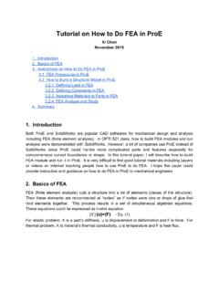
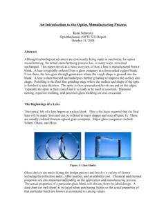
1 OPTI521 Fall 2009 Report tutorial Distance Learning Koichi Taniguchi Page. 1 / 10 Nov. 2009 A tutorial for designing fundamental imaging systems Koichi Taniguchi OPTI 521 Distance Learning College of Optical Science University of Arizona November 2009 Abstract This tutorial shows what to do when we design opto-mechanical system for imaging system. Basic principles about designing paraxial systems are introduced. In particular, you can find how to decide specifications, how to select optical elements, how to calculate image shift and how to estimate wavefront errors. Introduction Optical elements have been developed due to development of manufacturing tools, and we can use various kinds of mirrors, lenses, prisms or filters in various systems , and we can get high-quality elements. When we develop optical systems , we need to decide specifications according to cost, size or image quality. is an example of imaging microscope optical system.
2 This includes features which we have to decide when we are designing basic optical systems . FiltersObjective lensApertue stopWavefront aberrationElement surface error,Material internal defectsTilt,Lateral shiftLOSI maging lensCollimated rayImaging DeviceScattered orreflected lightObject An example of imaging microscope optical system OPTI521 Fall 2009 Report tutorial Distance Learning Koichi Taniguchi Page. 2 / 10 Nov. 2009 Specifications of optical system with imaging devices When we design optical systems , we need to decide specifications of optical systems . We need to decide following basic specifications, (1) Magnification and focal length, (2) Resolution and depth of focus. (1)(1)(1)(1) Magnification and focal lengthMagnification and focal lengthMagnification and focal lengthMagnification and focal length We should decide magnification of designed system according to the resolution of the image. We should decide it at first.
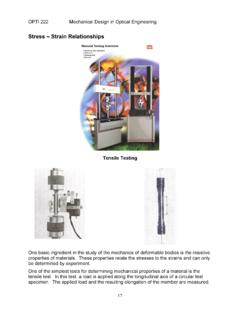
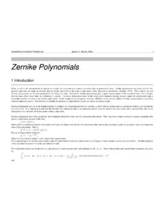
3 Magnification for fundamental optical system is shown in There are 2 lenses and object with height of ho. Object is placed at front focal plane of an objective lens, and an image is given at back focal plane of an imaging lens. Magnification of this optical system mmmm is given by the following equation[1]. This shows that we can calculate back focal length fifififi after we decide front focal length fifififi and magnification mmmm. The distance between the objective lens and imaging lens need not to be ffffoooo+f+f+f+fiiii because the ray is collimated between the 2 lenses. The image height is independent of this distance. hohifofififoObjective lensImaging lensCollimated rayFront focal plane of objective lensBack focal plane of imaging lensObjectImage Figure. The fundamental optical system with 2 lenses (2)(2)(2)(2) Resolution and depth of focus ( DoF )Resolution and depth of focus ( DoF )Resolution and depth of focus ( DoF )Resolution and depth of focus ( DoF ) Resolution and depth of focus ( DoF) depend on system F#.
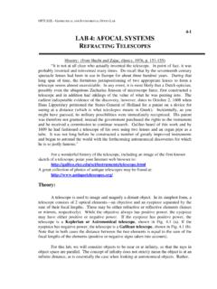
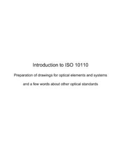
4 F# is important factor for image brightness and resolution of optical system, which is defined by following equation. We can get higher resolution with larger F#, but the depth of focus (DoF) becomes shorter. We have to balance both the DoF and resolution. There are 2 pictures taken with different F# in The background is focused in The picture because the camera with large F# has long DoF. On the other hand, the background is defocused in the picture because the camera with small F# has short OPTI521 Fall 2009 Report tutorial Distance Learning Koichi Taniguchi Page. 3 / 10 Nov. 2009 DoF. We use aperture stop in order to control F#. Where ffff is the focal length of optical element, and DDDD is the diameter. Resolution is also decided with F#. We can get high resolution with small F#. The resolution is described with Airy disc, explained in Airy disc is the size of image of a small point. The size of Airy disc is given by following equation.
5 The resolution of optical system is often described by the Airy disc. Where d is diameter of Airy disc. Resolution is a minimum distance in which two points can be distinguished, which is explained in Resolution is almost the same size as the size of the Airy disc. Picture with large F#(left, ) and with large F#(right, f/32) (Image by Wikipedia) d Airy discSmall point(Ideal point)Scattered ray( not condenced)Energy intensityScreen d Airy discSmall point(Ideal point)Scattered ray( not condenced)Energy intensityScreen Small Airy disc with large lens Large Airy disc with small lens Airy disc >dDifferent pointsDistinguishable distance Resolution of optics and Airy disc OPTI521 Fall 2009 Report tutorial Distance Learning Koichi Taniguchi Page. 4 / 10 Nov. 2009 Optical elements After we decide optical specifications, we need to think of what optical elements to use. (1)(1)(1)(1) Lens, mirrors and prismsLens, mirrors and prismsLens, mirrors and prismsLens, mirrors and prisms Lens, mirrors and prisms are most basic optical elements.
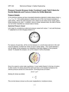
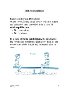
6 These deviate rays and we can condense rays or rotate images. At first we decide what lens to use and calculate focal length or other basic features. (2)(2)(2)(2) Image sensorImage sensorImage sensorImage sensor ( Photo detector ) ( Photo detector ) ( Photo detector ) ( Photo detector ) Image sensor transfers light energy to electrical energy. There are various kinds of sensors such as CMOS and CCD sensors, and it provides with each merit.[3][8] CCD or CMOS sensor is used for imaging devices such as digital camera or digital photo copier. PMT is a very high sensitivity photo detector which is used for detection few photon.[8] shows merit and demerit of each sensor. We usually use CCD area sensors for imaging systems . CCD, CMOS image sensor and PMT is shown in CCD and CMOS is almost the same size, but PMT is much larger. Image sensor type MeritDemeritCCD(charge coupleddevice)high sensitivity,low noisehigh power consumption,high driving voltage,various power supply,difficult to manufactureCMOS(complementarymetal oxidesemiconductor)low power consumption,easy to manufacture,no smearlow sensitivity,fixed patteren noise,PMT(photo multiplier) very high sensitivitylarger than CCD or CMOS, (a) CCD (b) CMOS (C) PMT Image sensors ( Photo detectors ) (Image by Wikipedia,Hamamatsu)[3][8] (3)(3)(3)(3) FiltersFiltersFiltersFilters Filters are used to attenuate specific wavelength of rays.
7 We should use filters when we want to control brightness or colors of images, or need to detect specific wavelength. There are various kinds of filters such as band-pass filter that attenuate excluding OPTI521 Fall 2009 Report tutorial Distance Learning Koichi Taniguchi Page. 5 / 10 Nov. 2009 specific wavelength rays.[3] ND filter attenuates thoroughly over a wide wavelength band, so we can control amount of rays without changing system F#. Sharp cutting filters that cut outside inferred ray or outside. Because of these features, these filters look like colored glass window. Light transmission spectrum of each filter is shown in PL(polarized light) filter can pass a specific polarized light, which is used to suppress reflected light and you can see them used for sunglasses or camera filter which can suppress reflected light from surface of water or other reflective surfaces. We can find many other filters from optical components manufacturer website and need to choose appropriate filters according to our purpose.
8 [4]-[6] (a) Sharp-cutting filter (b) ND filter (c) Band-pass filter Spectrum of band-pass filter(for 500nm) (Image by Asahi-Spectra Co. LTD)[4] (4)(4)(4)(4) Aperture stopAperture stopAperture stopAperture stop Aperture stop is used in optical systems in order to change system F# to limit light amount to control the brightness of the images, DoF and resolution. Aperture stop is shown in Aperture stop is placed to limit amount of light most effectively. ObjectImageAperture stopRayFront focal planeBack focal plane Aperture stop ( Image by Wikipedia) [3] Aperture stop position Aperture stop <F#> <F#> <F#> <F#>smaller larger<Image brightness> <Image brightness> <Image brightness> <Image brightness>brigher darker<DoF> <DoF> <DoF> <DoF>shorer longer<Resolution> <Resolution> <Resolution> <Resolution>higher lower OPTI521 Fall 2009 Report tutorial Distance Learning Koichi Taniguchi Page.
9 6 / 10 Nov. 2009 (5)(5)(5)(5) AAAA djustments and mountsdjustments and mountsdjustments and mountsdjustments and mounts We need to consider adjusting optical components with precision. It is necessary to balance precision and cost. There are various kinds of kinematic mounts. It is preferable to decide it in consideration of the method of the mount and the processing cost. shows kinematic mirror holders. Kinematic mounts are often used for adjustment of element tilt. These are used for adjustment of mirror itself, but it is difficult for small lens system like a camera. Therefore it is desirable to loosen tilt error. (a) shows the structure of kinematic mount for 2-axis tilt. The ball constrains the motion of the optical element. (b) shows the ball constraints. These provide translation constraint, XYZ motion, but rotational motion is free. Kinematic mounts realize tilt or other necessary motion with these constraint structures.
10 (a)2 axis tilt (b)tilt and rotate Kinematic holder (Image by SIGMA KOKI CO. LTD)[6] (a) Structure of kinematic mounts (b) Constraint with ball Principle of kinematic mount[1]<Constraint number of D<Constraint number of D<Constraint number of D<Constraint number of DOOOOF>F>F>F> 1-DOF 2-DOF 3-DOF <available <available <available <available DOF>DOF>DOF>DOF> 5-DOF 4-DOF 3-DOF OPTI521 Fall 2009 Report tutorial Distance Learning Koichi Taniguchi Page. 7 / 10 Nov. 2009 Line of sight (LOS) In design of optical system, lateral shift or angular deviation of LOS correspond to the image motion. It is necessary to minimize the image motion and optimize element position error. We need to think of 6 factor of element motion, which is shown in Motion TypeLOS angle Image shift(1)Tilt(2)Lateral shift(3)Tilt(4)Lateral shift(5)Tilt(6)Lateral shiftLens motionMirror motionFilter motions System LOS change with optical element motion OPTI521 Fall 2009 Report tutorial Distance Learning Koichi Taniguchi Page.