Transcription of Temperature Sensor Theory - Smart Sensors
1 4 2003 Smart Sensors , Sensor TheorySeebeck EffectSeebeck circuit showing the positive (kp) and negative (kn) of a ChromelAlumel thermocouple. If the temperatures (T1 and T2) are different at the twojunctions a current will flow in the was responsible for developing the most rugged andsimplistic yet cost effective way of measuring Temperature over abroad range. Copper Constantan, Chromel Alumel, IronConstantan and Chromel Constantan, the standard thermo-couple calibrations that are in use today, were derived from thisresearch. They work the same way the scientist s Theory said theywould work. When you apply heat to T1 and T2 is at a differenttemperature the two dissimilar metals will produce a EMF. TheEMF is different for different metals and unfortunately it is notlinear, but it is accurate enough to handle most process applica-tions. Accuracy improvements have been made primarily bycloser control of the chemical composition; today thermocoupleshave accuracy as low as 1/2 degree Fahrenheit.
2 There havebeen other calibrations introduced since then and manyimprovements to the way thermocouples are used; but the creditfor developing thermocouples as we use them today goes toThomas few years later, Jean Peltier made the second most importantcontribution to thermocouple Theory . In essence he discoveredthat when heat flows across a thermoelectric junction, heat iseither absorbed or liberated. The direction of the current flowdictates whether the heat is absorbed or liberated. If the currentproduced by the Seebeck Effect is at the hotter of the twojunctions, heat is absorbed, while heat is liberated at the cooleror cold junction. He discovered this phenomena withoutdrinking a single cup of are many different types of Temperature Sensors . We willdeal with the two most common types, thermocouples and because they are the most common, but because these twoare the only two types Smart Sensors makes. (So if you arecurious about other Sensors , you will have to go elsewhere tofind out how they work).
3 Thermocouples - How do they work?In 1821 Thomas Seebeck, while making a pot of tea, discoveredthat when two dissimilar metals are joined together, a currentflows, as long as the Temperature at one of the junctions is at ahigher Temperature than the other junction. Little did he know, ashe finished his tea, that he would be famous for discovering thecurrent that flowed in this circuit and the EMF (Electro MotiveForce) that produced this current would be forever called theSeebeck two guys really developed the rules for the proper use ofthermocouples. First, and most important, is that the EMFdeveloped by the joining (hot junction) of two dissimilar metalswill report the Temperature at that junction regardless of thetemperature along the length of the wires. Second, and mypersonal favorite, is that the introduction of a third metal in thecircuit can cause unwanted variances in the EMF unless thesame Temperature is maintained along the entire length wherethe third metal is introduced. This means that all you thermo-couple users can not use cheap baling wire to make yourconnections to the instrument.
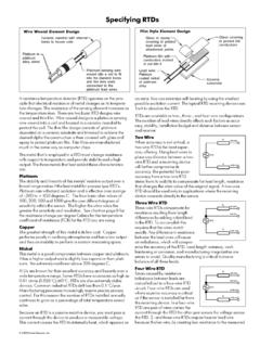
4 Third, quite simply stated this ruleallows the EMF signal to be brought back to a standardreference junction, usually 32 F, without maintaining intermedi-ate reference junctions at a constant diagram above has three junctions. The hot or measuringjunction T1 reports the furnace Temperature . A and B are theprimary positive and negative thermocouple elements. Asecondary junction Ts is used to transition to thermocoupleextension wire. This is done to reduce the cost of the thermo-couple circuit. The cost of MI cable is several times moreexpensive than thermocouple extension wire. Certain applica-tions require the flexibility that only thermocouple extension wirecan bring. Finally T2 as the reference junction connects thethermocouple to the instrument. Seebeck and Peltier discoveredthat if T1 and T2 are at the same Temperature there will be nocurrent flow in the and Advanced ThermocouplesWhen it comes right down to it there are only two basic types ofthermocouple constructions. One is the kind our old friendsPeltier and Seebeck used: Two dissimilar wires with a junctionand insulated from one another.
5 This is the most rudimentaryconstruction and it can work given the simplicity of the applica-tion. Second and let s get modern here; the mineral insulatedcable design that SSi type uses a high purity magnesium oxide (MgO) to insulatethe thermocouple wires from each other and the sheath. Thisinsulation possesses high insulation resistance and uppertemperature limits that far exceed the usable range of standardgrade thermocouples. It is densely packed within a metallicsheath to insure concentric positioning of the conductors andimproved mechanical strength, even when exposed to mechani-cal pressures such as bending, twisting or