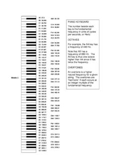
Transcription of Revision E By Tom Irvine January 26, 2015 CL - …
1 1 RING VIBRATION MODES Revision E By Tom Irvine Email: January 26, 2015 Variables C torsion constant CL longitudinal wave speed d diameter E elastic modulus G shear modulus fn natural frequency f r ring frequency h height Ix, Iy cross-sectional area moment of inertia m mass per arc length t thickness mass per volume Poisson ratio Ring Frequency Consider a ring with a rectangular cross section and with completely free boundary conditions. 2 The ring frequency corresponds to the mode in which all points move radially outward together and then radially inward together. This is the first extension mode. It is analogous to a longitudinal mode in a rod. The ring frequency rfis the frequency at which the longitudinal wavelength in the skin material is equal to the vehicle circumference.
2 DCfLr (1) Note that the wave speed can be calculated as ECL (2) The longitudinal wave speed in aluminum is approximately 16,700 feet per second. Thus the ring frequency for aluminum is dHzft5316fr (3) dHzin790,63fr (4) Note that the ring frequency mode is a higher mode. It occurs at a much higher frequency than the first few bending modes. Equations (1) through (4) are taken from Reference 1. In-plane Bending Mode The natural frequency equation for the in-plane bending modes is ,3,2,1n,mIE1nd1nn2fny222 (5) 3 Note that the Y-axis is the longitudinal axis, with its origin at the center of the cross-section.
3 Equation (5) is taken from Reference 2. Note that the n=1 case corresponds to in-plane rigid-body translation, with a frequency of zero. The area moment of inertia for a thin ring is 3yth121I (6) By substitution, ,3,2,1n,th121mE1nd1nn2fn3222 (7) Note that thm (8) By substitution, ,3,2,1n,th121thE1nd1nn2fn3222 (9) ,3,2,1n,tE311nd1nnfn2222 (10) 4 Out-of-Plane Bending Mode The natural frequency equation for the out-of-plane bending modes is ,3,2,1n,CGIEnmIEd1nn2fnx2x22 (11) Equation (11) is taken from Reference 2.
4 Note that the n=1 case corresponds to out-of-plane rigid-body translation, with a frequency of zero. For a rectangular cross section, 3xht121I (12) ,3,2,1n,CGEht121nmEht121d1nn2fn32322 (13) ,3,2,1n,CGEhtn12mEhtd1nn2fn32322 (14) 5 ,3,2,1n,CGEhtn12thEhtd1nn2fn32322 (15) ,3,2,1n,CGEhtn12 Edh1nn2fn3222 (16) 12GE (17) By substitution, ,3,2,1n,C1ht2n12 Edh1nn2fn3222 (18) The torsion constant for a rectangular cross-section is taken as (19)
5 6 By substitution, ,3,2,1n, (20) ,3,2,1n,1 (21) Model A finite element was constructed as shown in Figure 1 and in Table 1. Table 1. Model Parameters Parameter Value Number of Nodes 5040 Number of Elements 2016 Element Type Solid Thickness inch Height inch Diameter 40 inch Boundary Condition Completely Free Material Aluminum Mass Density lbm/in^3 Elastic Modulus 9900000. lbf/in^2 Software FEMAP and NE/Nastran The results of the finite element analysis are given in Figures 2 through 4. The numerical results are summarized in Table 2, along with the theoretical values. 7 Figure 1. Undeformed Model Figure 2. First In-plane Bending Mode, Superimposed on Undeformed Model, Frequency = Hz 8 Figure 3. First Out-of-Plane Bending Mode, Superimposed on Undeformed Model, Frequency = Hz Figure 4.
6 First Extensional Mode, Superimposed on Undeformed Model, Frequency = 1581 Hz 9 Table 2. Finite Element Model Results Mode FEM Frequency (Hz) Theoretical Frequency (Hz) Theoretical Equation First In-plane Bending (5) First Out-of-plane Bending (11) First Extensional (Ring Frequency) 1581. 1595. (1) The agreement is very good for each case. First In-plane Bending Mode Hand Calculation The natural frequency equation for the in-plane bending modes is ,3,2,1n,mIE1nd1nn2fny222 (22) For n=1, 0fn (23) For n=2, mIE5d12fny2 (24) The area moment of inertia for a thin ring is 3yth121I (25) 10 ) )(in1(121I (26) The mass per arc length is lbm386/insec (27) (28) References 1.
7 T. Irvine , Vibration Response of a Cylindrical Skin to Acoustic Pressure via the Franken Method, Vibrationdata Publications, 2002. 2. R. Blevins, Formulas for Natural Frequency and Mode Shape, Krieger, Malabar, Florida, 1979. 3. Weaver, Timoshenko, and Young; Vibration Problems in Engineering, Wiley-Interscience, New York, 1990. 11 APPENDIX A Extensional Vibration of a Ring The derivation is taken from Reference 3. u is the radial displacement E is the modulus of elasticity A is the cross-sectional area r is the radius d is the diameter is the mass/length c is the speed of sound in the material The potential energy U is r22r22uAEU (A-1) 2urAEU (A-2) The kinetic energy T is r22u2AT (A-3) 2uArT (A-4) 12 Apply the energy method.
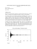
8 0 UTdtd (A-5) 02urAE2uArdtd (A-6) 0uurAE2uuAr2 (A-7) 0urEur (A-8) 0u2rEu (A-9) 0u2nu (A-10) 2rE2n (A-11) 2rEn (A-12) 13 Er1n (A-13) Er21nf (A-14) dcnf (A-15) Ec (A-16) 14 APPENDIX B Fairing Ring Frequency Excited during Pyrotechnic Shock DataTIME (SEC)ACCEL (G)ACCEL (G) 92 INCH FAIRING SEPARATION TEST B3 RADIAL FAIRING FWD OF SEP SOURCE RAIL EVENT Figure B-1.
9 The source device was a frangible joint rail. The data was measured during a ground test. The fairing consists of graphite-epoxy skins over an aluminum honeycomb core. Note that the data is bandpass filtered from 20 to 2000 Hz. 15 The fairing s ring frequency is dLCfn (B-1) LC = 257,976 in/sec Longitudinal wave speed in the composite skin material d = 92 in Diameter in92in/sec257,976fn = 893 Hz The synthesis consists of ten components. The first three are given in Table B-1. Table B-1. Synthesis Results N Amp (G) Freq (Hz) Phase (rad) Damping Delay (sec) 1 2 3 The second component represents the ring frequency.
10