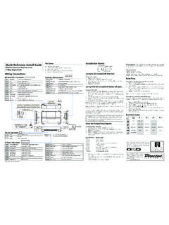
Transcription of 5305 and 5105 Installation Guide LCD 2-way and 1-way ...
1 5305 and 5105 Installation GuideLCD 2-way and 1-way modelsSecurity and remote start This product is intended for Installation by a professional installer only! Attempts to install this product by a per-son other than a trained professional may result in severe damage to a vehicle s electrical system and components. 2015 Directed, Vista, CA N5X05 2016-01 Bitwriters with a date code of 6A or older require an IC upgrade (P/N 998M). Some Bitwriters with a date code of 6B do not require the IC upgrade, refer to Tech Tip # 1112 for more infor-mation. Bitwriter , Code Hopping , Doubleguard , ESP , Fail-Safe , Ghost Switch , Learn Routine , Nuisance Preven-tion Circuitry, Revenger , Silent Mode , Soft Chirp , Stinger , Valet , VRS , and Warn Away are all Trade-marks or Registered Trademarks of Directed.
2 The Bitwriter (P/N 998U) requires chip version or newer to program this ! Safety First ..4 Wiring Diagram ..5 Wiring Connections ..6 Main Harness, White 5-pin connector ..6 Auxiliary/Shutdown/Trigger Harness, White 24-pin connector ..6 remote start , White 10-pin heavy gauge connector ..7 Door Lock, White 3-pin connector ..7 Wire Descriptions ..7 Main Harness, White 5-pin connector ..7 Auxiliary/Shutdown/Trigger Harness, 24-pin connector ..8 remote start Heavy Gauge Harness, 10-pin connector ..10 Door Lock, 3-pin connector ..11 Connecting the Doubleguard Shock Sensor ..12 Adjusting the Doubleguard Shock Sensor ..13 Initializing Virtual Tach (not needed w/analog or data tach inputs) ..13 Learning Analog or Data Tach (not needed with Virtual Tach) ..13 remote start Shutdown Diagnostics ..14 Pairing a remote Control.
3 15 Basic remote Functions ..15 Programming System Features ..15 Feature Menus ..17 Menu 1 - Basic ..17 Menu 1 - Descriptions ..17 Menu 2 - Descriptions ..19 Menu 3 - remote start ..21 Menu 3 - Descriptions ..21 Bitwriter - Only Options ..23 Bitwriter Feature Descriptions ..23 Reset and Deletion ..24 security Features Disable/Enable ..25 Long Term Event History ..25 Table of Zones ..26 Troubleshooting: Alarm ..26 Troubleshooting: remote start ..274 2015 Directed. All rights ! Safety FirstThe following safety warnings must be observed at all times: Due to the complexity of this system, Installation of this product must only be performed by an authorized Directed dealer. When properly installed, this system can start the vehicle via a command signal from the remote control. Therefore, never operate the system in an area that does not have adequate ventilation.
4 The following precautions are the sole responsibility of the user; however, authorized Directed dealers should: Never use a test light or logic probe when installing this unit. Always use a multimeter. Never operate the system in an enclosed or partially enclosed area without ventilation (such as a ga-rage). When parking in an enclosed or partially enclosed area or when having the vehicle serviced, the remote start system must be disabled using the installed toggle switch. It is the user s sole responsibility to prop-erly handle and keep out of reach from children all remote controls to assure that the system does not unintentionally remote start the vehicle. USER MUST INSTALL A CARBON MONOXIDE DETECTOR IN OR ABOUT THE LIVING AREA ADJACENT TO THE VEHICLE. ALL DOORS LEADING FROM ADJACENT LIVING AREAS TO THE ENCLOSED OR PAR-TIALLY ENCLOSED VEHICLE STORAGE AREA MUST REMAIN CLOSED AT ALL of this product in a manner contrary to its intended mode of operation may result in property damage, personal injury, or death.
5 Except when performing the Safety Check outlined in this Installation Guide , (1) Never remotely start the vehicle with the vehicle in gear, and (2) Never remotely start the vehicle with the keys in the ignition. The user is responsible for having the parking brake/emergency brake feature of the vehicle periodically checked, wherein the vehicle must not remotely start while the car is in gear. This testing should be performed by an authorized Directed dealer in accordance with the Safety Check outlined in this product Installation Guide . If the vehicle starts in gear, cease remote start operation immediately and consult with the user to fix the problem the remote start module has been installed, test the remote start module in accordance with the Safety Check outlined in this Installation Guide . If the vehicle starts when performing the Neutral Safety Shutdown Circuit test, the remote start unit has not been properly installed.
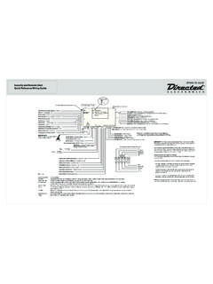
6 The remote start module must be removed or properly reinstalled so that the vehicle does not start in gear. All installations must be performed by an authorized Directed dealer. OPERATION OF THE remote start MODULE IF THE VEHICLE STARTS IN GEAR IS CONTRARY TO ITS IN-TENDED MODE OF OPERATION. OPERATING THE remote start SYSTEM UNDER THESE CONDITIONS MAY RESULT IN PROPERTY DAMAGE OR PERSONAL INJURY. IMMEDIATELY CEASE THE USE OF THE UNIT AND REPAIR OR DISCONNECT THE INSTALLED remote start MODULE. DIRECTED WILL NOT BE HELD RESPONSIBLE OR PAY FOR Installation OR REINSTALLATION product should not be installed in any manual transmission vehicles. Installation in such vehicles may pose certain 2015 Directed. All rights Diagram 5X05 remote Start10-pin HarnessMain 5-pinHarnessDoor Lock3-pinHarnessLight FlashPolarity Jumper(-/+)OnboardThermistorTemp SensorAUX/Shutdown/Trigger24-pin HarnessRF Port/Control CenterBitwriter/Directed SmartStart PortDoubleguard Shock Sensor PortD2D Port (for externalDirected interface Module)Note: (+) or (-) light ash jumper needs to be installed for the appropriatelight ash polarity and is found taped to the outside on the main unit.
7 6 2015 Directed. All rights ConnectionsMain Harness, White 5-pin connector 1 BLACK(-) CHASSIS GROUND2 BROWN(+) SIREN OUTPUT 3 RED(+) FUSED 12V DC CONSTANT INPUT4 ORANGE(-) 500mA GWA (GROUND WHEN ARMED) OUTPUT5 WHITE (+)/(-) SELECTABLE PARKING LIGHT OUTPUT (FUSED)Auxiliary/Shutdown/Trigger Harness, White 24-pin connector135 WIRE SIDE2462423 PINK/WHITEVIOLET/WHITEGREEN/WHITEBLACK/W HITE123 WIRE SIDE132412 PINK/WHITEVIOLET/WHITEGREEN/WHITEBLACK/W HITE1 PNK/WHITE(-) 200mA IGNITION 2/ACCESSORY OUTPUT2 BLUE/WHITE(-) 200mA 2ND STATUS /REAR DEFOGGER OUTPUT3 RED/WHITE(-) 200mA TRUNK RELEASE OUTPUT4 BLACK/YELLOW(-) 200mA DOME LIGHT OUTPUT5 DARK BLUE(-) 200mA STATUS OUTPUT6 WHITE/BLACK(-) 200mA AUX 5 OUTPUT7 WHITE/VIOLET(-) 200mA 2nd UNLOCK OUTPUT8 ORANGE/BLACK(-) 200mA AUX 6 OUTPUT9 GRAY(-) HOOD PIN INPUT10 BLUE(-) TRUNK PIN/INSTANT TRIGGER INPUT11 WHITE/BLUE **(-) remote start ACTIVATION INPUT12 VIOLET/WHITETACHOMETER INPUT13 BLACK/WHITE*(-) PARKING BRAKE INPUT/EMERGENCY INPUT14 GREEN/BLACK (-) 200mA FACTORY ALARM DISARM OUTPUT15 GREEN(-) DOOR INPUT 16 BROWN/BLACK(-) 200mA HORN HONK OUTPUT17 PINK(-) 200mA IGNITION 1 OUTPUT18 VIOLET(+) DOOR INPUT19 VIOLET/BLACK(-) 200mA AUX 4 OUTPUT20 BROWN(+) BRAKE SHUTDOWN INPUT21 VIOLET/YELLOW(-) 200mA STARTER OUTPUT22 GRAY/BLACK (-) DIESEL WTS (WAIT-TO- start ) INPUT23 ORANGE(-) 200mA ACCESSORY OUTPUT24 GREEN/WHITE(-) 200mA FACTORY ALARM ARM OUTPUT* Connect this wire to one of the wires on the provided remote start Shutoff Switch.
8 The other wire on the switch connects to the (-) Parking Brake/Emergency Brake wire in the vehicle. The switch must be in the ON position for the remote start to work.** This wire not only activates the remote start , it can also be used to change feature options when pro-gramming. See Programming System : NEVER connect 200mA low current outputs directly to a motor or high current device WITHOUT a 2015 Directed. All rights start , White 10-pin heavy gauge connector1 No Connection2 RED/BLACK(+) FUSED 12V ACCESSORY/STARTER INPUT3 PINK/BLACK*(+) IGNITION 2/ACCESSORY ISOLATION WIRE # 87A key side (if required) of IGNITION 2/ACCESSORY4 PINK/WHITE(+) IGNITION 2 / ACCESSORY RELAY OUTPUT5 RED(+) FUSED 12V IGNITION 1 INPUT6 GREEN(+) STARTER INPUT (KEY SIDE OF THE STARTER DISABLE)7 VIOLET(+) STARTER OUTPUT (CAR SIDE OF THE STARTER DISABLE)8 ORANGE(+) ACCESSORY OUTPUT9 RED/WHITE(+) FUSED 12V IGNITION 2 / FLEX RELAY INPUT 8710 PINK(+) IGNITION 1 INPUT/OUTPUT* This wire is only used in applications that require a specific circuit at the ignition switch to be isolated during the remote start Lock, White 3-pin connector1 BLUE(-) 500mA UNLOCK OUTPUT2 EMPTYNOT USED3 GREEN (-)
9 500mA LOCK OUTPUTD2D Harness, Red 4-pin connector1 BLUED2D - TX2 BLACK (-) GROUND3 GREEND2d - RX4 RED(+) 12 VBitwriter/Directed SmartStart Harness, Black 3-pin connector1 RED(+) 12V2 ORANGEESP 2 - RX/TX3 BLACK(+) 12 VWire DescriptionsMain Harness, White 5-pin connectorBlack: (-) CHASSIS GROUNDThis wire is the unit s source of ground. DO NOT connect this wire to any factory ground points; they can cause noise and/or voltage drops which can affect system performance. Ground the unit and any accesso-ries to the same point in the vehicle (preferably the kick panel). Scrape away any paint and make your own ground with a screw and a star : (+) SIREN OUTPUTThis wire is the (+) output for the siren. This wire connects to the (+) input of the : (+) 12V CONSTANT INPUTThis wire supplies power to the unit s micro-controller. Remove the supplied fuse before connecting to the (+) terminal of the battery or another constant +12V supply.
10 Make sure to replace the fuse when all connections have been made. Note: Always use a fuse within 12 inches of the point from which you obtain (+) 12V. Do not use the 15A fuse in the harness for this purpose. This fuse protects the module 2015 Directed. All rights : (-) GWA (GROUND WHEN ARMED) OUTPUTThis wire supplies a (-) 500mA ground output as long as the system is armed and while the remote start is active. This output ceases as soon as the system is disarmed or remote start disengages. The GWA can be hooked up to a voice module or any accessory which requires a ground when : The Ground When Armed during remote start feature can be programmed off (see Anti-grind Output in Feature Menus for more detail).White: (+) or (-) PARKING LIGHTS OUTPUTThis wire should be connected to the parking lights wire in the vehicle.