Transcription of Proportional directional valves type DPZO-LES
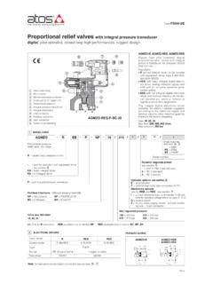
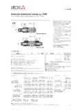
1 Proportional directional valves high performance piloted, with two LVDT transducers and positive spool overlapDPZO-L-271 Proportional directional valve, pilotedValve size ISO 4401: 1 = 10 2 = 16 4 = 25 4M = 27 6 = 32 Nominal flow (l/min) at p 10bar P-TAB DPZO-L Proportional directional valves , piloted, with two LVDT position transducers and positive spool overlap for best dynamics in directional controls and not compensated flow regulations. The valves operate in association with digi-tal off-board divers, see section . The two LVDT transducers (pilot and main stage) grant very high regulation accuracy and response sensitivity. With de-energized Proportional solenoids, mechanical central position of the spool is performed by centering springs Spools regulation characteristics: L = linear S = progressive for fine low flow control D and DL = differential, for control of actua-tors with area ratio 1:2 D9 and L9 = for regenerative circuit Q5 and V9 = for alternate P/Q control Size: 10 32 - ISO 4401 Max flow: 180 1600 l/min Max pressure: 350 bar371 =73 =Option /BStandardDPZO-1 = DPZO-2 = DPZO-4 = DPZO-4M = DPZO-6 =Spool size:F175 Valve body Main stage Spool Pilot valve Pilot valve LVDT transducer Main stage LVDT transducer Pilot valve solenoid Table F175-19/EConfiguration:(2) Spools for regenerative circuit or alternated P/Q control, see section (3) All combination possible 2 Series numberDPZO-/-1 MODEL CODE OF STANDARD SPOOLSS eals material, see section.
2 - = NBR PE = FKM BT = HNBR7271L5**/*-LL = two LVDT transducersSpool type, regulating characteristics (2): L = linearS = progressive D = differential-progressive P-A = Q, B-T = Q/2 P-B = Q/2, A-T = QDL = differential-linear P-A = Q, B-T = Q/2 P-B = Q/2, A-T = Q Hydraulic options (3): B = solenoid and LVDT transducer at side of port B of the main stage (side A of pilot valve) D = internal drain E = external pilot pressure G = pressure reducing valve for piloting72 =(1) Only for DPZO sizes 2, 4, 4M with spools L5 or S5: in central position the leakages P-A and P-B are drained to tank, avoiding the drift of cylinders with differential areas (1)Spool type:Configuration: 100 250 480 550 - - 160 - - - - - - - 6403L, S, D71, 735L, DL, S, D71, 735L, S, D71, 73 - 250 480 550 -5L, S724 GENERAL CHARACTERISTICS3 OFF-BOARD ELECTRONIC DRIVERSP lease include in the driver order also the complete code of the connected Proportional CODE OF SPOOLS FOR REGENERATIVE CIRCUIT OR ALTERNATED P/Q CONTROL - for valve model code and options, see sect.
3 1 DPZO//-L271 - L9**-71-D971-L973-D973-L973-Q573-V9 Nominal flow (l/min) at p 10bar P-TSpool size: DPZO-1 = DPZO-2 = DPZO-4 = DPZO-4M = DPZO-6 =Configuration and spool for regenerative circuit:D9 100 250 480 550 -L9 - 250 - - -V9 100 250 480 550 640Q5 100 250 480 550 -D9L9Q5V9 For regenerative circuit (additional external check valve required) see - diagram 26 For regenerative circuit internal to the valve see - diagram 27 For alternated P/Q control see - diagram 28 For alternated P/Q control of injection cycle in plastic machinery see - diagram 29 Configuration and spool for alternated P/Q control:Drivers modelE-BM-LIDE-BM-LEBE-BM-LEST ypedigitaldigitaldigitalFormatDIN-rail panelDIN-rail panelDIN-rail panelTech tableGS235GS230GS240 Assembly positionAny positionSubplate surface finishing to ISO 4401 Acceptable roughness index: Ra 0,8, recommended Ra 0,4 Flatness ratio 0,01/100 MTTFd valves according to EN ISO 1384975 years, see technical table P007 Ambient temperature rangeStandard = -20 C +60 C /PE option = -20 C +60 C /BT option = -40 C +60 CStorage temperature rangeStandard = -20 C +70 C /PE option = -20 C +70 C /BT option = -40 C +70 CSurface protectionZinc coating with black passivationCorrosion resistanceSalt spray test (EN ISO 9227) > 200 hComplianceCE according to EMC directive 2014/30/EU (Immunity: EN 61000-6-2; Emission: EN 61000-6-3) RoHS Directive 2011/65/EU as last update by 2015/65/EU REACH Regulation (EC) n 1907/2006 F175zero point displacement < 1% at T = 40 Cports P, A, B, X = 350; T = 250 (10 for option /D); Y = 10.
4 0,1 [% of max regulation] 0,1 [% of max regulation] 50 80 90 60 851001,71601803,74806,883010005508950110 064014,411001600min. = 25; max = 350 (option /G advisable for pilot pressure > 200 bar)Hysteresis Repeatability Thermal driftResponse time (4)[ms] Leakage (3) Pressure limits[bar]Valve modelDPZO-L-1 DPZO-L-2 DPZO-L-4 DPZO-L-6 DPZO-L-4 MPiloting flow[l/min]Piloting pressure[bar]250430550160270400(2)1,43,7 9,011,321,6100 / 300100 / 300200 / 500200 / 600900 / 28000,15 / 0,50,2 / 0,60,3 / 1,00,3 / 1,01,0 / 3,0 Piloting volume[cm3]L5, DL5, S5, D5standardL3, S3, D3L5, DL5, S5, D5L5, S5, D5 Pilot [cm3/min] Main stage [l/min]regenerative or P/QV9D9, V9, Q5D9, L9, V9, Q5D9, V9, Q5 Spool type (1) For different p, the max flow is in accordance to the diagrams in section (2) With step reference input signal 0 100 %5 HYDRAULIC CHARACTERISTICS - based on mineral oil ISO VG 46 at 50 C(3) At p = 100/350 bar (4)
5 0-100% step signal see detailed diagrams in section AND HYDRAULIC FLUIDS - for other fluids not included in below table, consult our technical office Seals, recommended fluid temperature NBR seals (standard) = -20 C +80 C, with HFC hydraulic fluids = -20 C +50 C FKM seals (/PE option) = -20 C +80 C HNBR seals (/BT option) = -40 C +60 C, with HFC hydraulic fluids = -40 C +50 C Recommended viscosity20 100 mm2/s - max allowed range 15 380 mm2/s Hydraulic fluidSuitable seals typeClassificationRef. Standard Mineral oilsNBR, FKM, HNBRHL, HLP, HLPD, HVLP, HVLPDDIN 51524 Flame resistant without waterFKMHFDU, HFDRISO 12922 Flame resistant with waterNBR, HNBRHFCMax fluid contamination level see also filter section at or KTF catalognormal operation longer lifeISO4406 class 18/16/13 NAS1638 class 7 ISO4406 class 16/14/11 NAS1638 class 56 ELECTRICAL CHARACTERISTICSMax power consumption30 WMax.
6 Solenoid current2,6 ACoil resistance R at 20 C3 3,3 Insulation classH (180 ) Due to the occuring surface temperatures of the solenoid coils, the European standards ISO 13732-1 and EN982 must be taken into accountProtection degree to DIN EN60529IP65 with mating connectorsDuty factorContinuous rating (ED=100%) p= 10 bar p= 30 barMax permissible flow[l/min]Nominal flow p P-T [l/min] (1) 8 DIAGRAMS (based on mineral oil ISO VG 46 at 50 C)Note: Hydraulic configuration vs. reference signal (standard and option /B) Reference signal 0 +10 V P n A / B n T 12 20 mAReference signal 0 -10 V P n B / A n T 12 4 mA }} Regulation diagrams (values measure at p 10 bar P-T)DPZO-1: 1 = L52A = DL5 (P n A, A n T) 3 = S52B = DL5 (P n B, B n T) 4A = D5 (P n A, A n T) 4B = D5 (P n B, B n T)89 BRegulated flow [l/min]Stroke [% of max]32B157A6101213B1415 BDPZO-4: 12 =L513A = DL5 (P n A, A n T) 14=S513B = DL5 (P n B, B n T) 15A = D5 (P n A, A n T) 15B = D5 (P n B, B n T)DPZO-6: 20 =L5 22A = D5 (P n A, A n T) 21 = S5 22B = D5 (P n B, B n T) DPZO-2: 5 = L37A = D3 (P n A, A n T) 6 = S37B = D3 (P n B, B n T) DPZO-4M: 16=L517A = DL5 (P n A, A n T) 18=S517B = DL5 (P n B, B n T) 19A = D5 (P n A, A n T) 19B = D5 (P n B, B n T)DPZO-2.
7 8=L5 9A = DL5 (P n A, A n T) 10=S5 9B = DL5 (P n B, B n T) 11A = D5 (P n A, A n T) 11B = D5 (P n B, B n T)Regulated flow [l/min]Regulated flow [l/min]Regulated flow [l/min]Regulated flow [l/min]Regulated flow [l/min]Stroke [% of max]Stroke [% of max]Stroke [% of max]Stroke [% of max]Stroke [% of max]4B32A14A57B611B89A1011A1213A1415A19B 1817B1619A1817A1622B212022A2120100806040 200-100 -80 -60 -40 -20 0 20 40 60 80 10020016012080400-100 -80 -60 -40 -20 0 20 40 60 80 100250200150100500-100 -80 -60 -40 -20 0 20 40 60 80 1005004003002001000-100 -80 -60 -40 -20 0 20 40 60 80 1006004803602401200-100 -80 -60 -40 -20 0 20 40 60 80 1006505203902601300-100 -80 -60 -40 -20 0 20 40 60 80 100 Regulated flow [% of max]Stroke [% of max]
8 23D9 spool type with a fourth position specific to regenerative circuit, performed by means of an additional external check = differential - regenerative spool D9 (not available for valve size 32 and 35)Application example24 = linear - internal regenerative spool L9 (available only for valve size 16)Stroke [% of max]Stroke [% of max]24L9 spool type with a fourth position specific to perform a regenerative circuit internal to the = differential - progressive spool V9 Regulated flow [% of max]26 Regulated flow [% of max]Stroke [% of max]2525 = linear spool Q5 (not available for valve size 32 and 35)Q5 spool type is specific for alternate P/Q con-trols in combination with /S* option of digital inte-gral drivers, (see tech. table FS500). It allows to control the pressure in A port or B port and it provides a safety central position (A-T/B-T ) to depressurize the actuator chambers.
9 The strong meter-in characteristic makes the spool suitable for both pressure control and motion regulations in several applications. rigenerativeRegulated flow [% of max]F175V9 spool type is specific for alternate P/Q controls in combination with S* option of digital integral dri-vers (see tech table FS500). This spool is specially designed to manage the whole injection cycle in plastic machinery, thanks to the following specific features: - strong meter-in characteristic to allow the pres-sure control in A port during the holding pressu-re (P-A) and the plasticizing (A-T) phases - safety central position (A-T/B-T) to depressurize the actuator chambers - large A-T and B-T flow capability, required during the plasticizing phase, to discharge big volumes from high differential injection cylinders with low pressure drops and permitting the con-temporary oil suction from tank100806040200-100 -80 -60 -40 -20 0 20 40 60 80 100100806040200-100 -80 -60 -40 -20 0 20 40 60 80 100100806040200-100 -80 -60 -40 -20 0 20 40 60 80 100100806040200-100 -80 -60 -40 -20 0 20 40 60 80 Response time The response times in below diagrams are measured at different steps of the reference input signal.
10 They have to be considered as average values. For the valves with digital electronics the dynamics performances can be optimized by setting the internal software : 1 = spools L5, S5, D5, DL5, D9, V9, Q5 Operating diagrams Flow / p diagram stated at 100% of spool stroke DPZO-2: 2 = spools L3, S3, D3 3 = spools L5, S5, D5, DL5, D9, L9, V9, Q5 DPZO-6: 6 = L5, S5, D5, V9 DPZO-4: 4 = spools L5, S5, D5, DL5, D9, V9, Q5 DPZO-4M: 5 = spools L5, S5, D5,DL5, D9, V9, Q5 Valve pressure drop p [bar]Valve pressure drop p [bar]Valve pressure drop p [bar]213456 Time [ms]Time [ms]Time [ms]Spool stroke [%]Spool stroke [%]Spool stroke [%]Step signal [%]Step signal [%]Step signal [%]DPZO-1 DPZO-2 DPZO-4 DPZO-4 MDPZO-6 Flow rate [l/min]Flow rate [l/min]Flow rate [l/min]103070100200300600 500 4003002001001400 1200 10008006004001030701002003003500 3000 25002000150010001030701002003000 -1000 -750 -500 -2510075502501530456075015304560750 -1000 -750 -500 -251007550250204060801000204060801000 -1000 -750 -500 -251007550250204060801000204060801009 HYDRAULIC OPTIONS Pilot valve Main stage Pressure reducing valve Plug to be added for external pilot trough port X Plug to be removed for internal drain through port T F175B = Solenoid and LVDT transducer at side of port B of the main stage (side A of pilot valve).