Transcription of Design of Compression Members (Part 4 of AISC/LRFD)
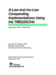
1 53:134 Structural Design II Design of Compression Members (Part 4 of AISC/LRFD) Euler Buckling of Columns Global buckling of a member happens when the member in Compression becomes unstable due to its slenderness and load. Buckling can be elastic (longer thin Members ) or inelastic (shorter Members ). Here we shall derive the Euler buckling (critical) load for an elastic column. Consider a long and slender Compression member (hinged) as shown in the figure above. The Euler buckling formula is derived for an ideal or perfect case, where it is assumed that the column is long, slender, straight, homogeneous, elastic, and is subjected to concentric axial compressive loads. The differential equation for the lateral displacement v is given as: Arora/Q.
2 Wang 153:134 Structural Design II PvMdxvdEI ==22 where E is the modulus of elasticity, I is the moment of inertia about the axis of bending in the cross section, P is the axial compressive force, and M is the bending moment at a distance x from support A. If we consider the column to be at the point of buckling, we have 022=+vEIPdxvdcr or , where 02=+ vkvEIPkcr=2 This is a second-order homogeneous linear differential equation with constant coefficients. The boundary conditions for the problem are also homogeneous as ()()0and00==Lvv The solution of the differential equation is kxCkxCvsincos21+= The integration constants and can be found by applying the following geometric boundary conditions: 1C2C At x = 0: 001= =Cv At x = L: 002= =kLsinCv The above equation indicates that either = 0, which means no lateral displacement at all, or 2C0sin=kL with solution nkL=="3,2, Therefore, is crP 222 LEInPcr = Arora/Q.
3 Wang 253:134 Structural Design II Various values of n correspond to different buckling loads. When , the smallest value obtained is known as critical load, buckling load, or Euler formula: 1=n 22 LEIPcr = Note that the critical buckling load is independent of the strength of the material (say, , the yield stress). This equation was obtained for a column with hinged ends. The equation can be used for columns with other end conditions, as follows: yF ()22 KLEIPcr = where KL is the distance between the points of zero moment, or inflection points along the length. The length KL is known as the effective length of the column. The dimensionless coefficient K is called the effective length factor. Dividing the critical load by the cross-sectional area of the column A, we can find the critical stress , as crPcrF ()()2222r/KLEAKLEIAPF crcr === where r is the radius of gyration of the cross section about the axis of bending (2 ArI=) and KL/r is called the slenderness ratio of the column.
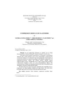
4 A thin column has small radius of gyration and a stocky column has large radius of gyration. The slenderness ratio determines elastic or inelastic mode of buckling failure. Columns with small slenderness ratios are called short columns. Short columns (small KL/r) do not buckle and simply fail by material yielding. Arora/Q. Wang 353:134 Structural Design II Long columns (large KL/r) usually fail by elastic buckling mentioned above. Between short and long regions, the failure of the column occurs through inelastic buckling. The figure shows the three types of failure modes for a column. If we define a slenderness parameter as ()crycF/F=2 EFrKLyc = Then the equation of the critical stress is crF()yccrFr/KLEF2221 == Note that 1 c . Notations: Arora/Q. Wang 453:134 Structural Design II c Resistance factor for Compression ( ) gA Gross cross-sectional area yF Specified minimum yield stress nP Nominal axial strength of the section uP Required axial strength E Modulus of elasticity K Effective length factor L Lateral unbraced length of the member r Governing radius of gyration Design Strength: ncP for Compression Members based on buckling failure mode The critical load is given as ()()ArI;r/KLEAKLEIPcr22222=== Buckling can take place about the strong (x) axis or the weak (y) axis.
5 Larger value for KL/r will give smaller critical load, and thus will govern the Design strength. Define yyyyxxxxrLK;rLK== Lx = unbraced length for bending about the strong axis Ly = unbraced length for bending about the weak axis If xy >, buckling about the y axis will govern the Design strength; , Arora/Q. Wang 553:134 Structural Design II xxxyyyrLKrLK> or yxxxyyr/rLKLK> How to Use Manual Table 4-2: Design strength in axial Compression is calculated as Table contains ncP for various values of KyLy, assuming buckling about y-axis. How to check buckling about x-axis: If yxxxyyr/rLKLK< buckling is about x-axis. How to read ncP if buckling is about x-axis: Use the length as yxxxr/rLK in Table 4-2. Design Procedure: 1. Calculate the factored Design loads . uP 2. From the column tables, determine the effective length KL using ()() =axisstrongaxisweakyxxxyyr/rLK,LKmaxKL and pick a section from Table 4-2.
6 Arora/Q. Wang 653:134 Structural Design II 3. Check the member thickness ratio in Table , if the member is not slender, use LRFD Chapter E2; otherwise, use LRFD Specifications Appendix E3 (reduction of Design strength by factor Q given in Appendix B of Specifications). 4. Check using Table 4-2 to 4-17: Calculate KL and enter into Table 4-2 to 4-17. Find the Design strength ncP . Or, using the formulas given in Chapter E2: The slenderness parameter is calculated as =EFrLK,EFrLKmaxyyyyyxxxc The critic al stress is calculated as <=)E(. )E(. 87702251for 6580c2c2 Arora/Q. Wang 753:134 Structural Design II The Design strength Required strength Design strength ncuPP Check for Slenderness Ratio: Slenderness ratio (recommendation) (SPEC B7) 200/ rKL Local Buckling Local buckling is an instability due to the plates of the member becoming unstable.
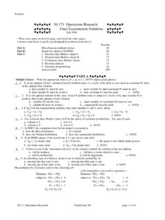
7 The local buckling of a member depends on its slenderness which is defined as the width-thickness ratio (b/t ratio), b is the width of the section and t is its thickness. Steel sections are classified as compact, noncompact or slender depending on the width-thickness ratio of their elements. Compact section: is capable of developing a fully plastic stress distribution and possess rotation capacity of approximately three before the onset of local buckling; , local buckling is not an issue. Noncompact section: can develop the yield stress in Compression elements before local buckling occurs, but will not resist inelastic local buckling at strain levels required for a fully plastic stress distribution. Local buckling can occur in the inelastic zone. Compact sections have small b/t ratio and do not buckle locally; noncompact section can buckle locally; slender sections have a large b/t ratio.
8 Let us define the width-thickness ration of an element of the cross-section (flange or web of WF shapes) as tb= Then the Members are classified as follows: Arora/Q. Wang 853:134 Structural Design II Compact section: p for all elements Noncompact sections: rp <. Slender: r >. The limiting values p and r for are given in Table of the LRFD Secifications. The strength corresponding to any buckling mode cannot be developed if the elements of the cross-section fail in local buckling. When b/t exceeds a limit r (Table of the LRFD Specifications), the member is classified as slender. Slender Members can fail in local buckling resulting in reduced Design strength. For slender Members , Appendix B of the LRFD Specifications describes the reduction factors Q to be used for calculation of the critical stress Fcr.
9 Basically, the Design strength needs to be reduced if the member is slender. Table of the LRFD Specifications defines the following limits for sections that are not slender: Unstiffened elements (flange): yrrffF/E.;tb5602= Stiffened element (web): yrrwF/E.;th491= Flexural-Torsional Buckling: Thin unsymmetrical Members can fail in flexural-torsional buckling under axial loads, such as angles, tees. Calculation of Design strength based on the flexural-torsional buckling failure mode is described in Section E3 and Appendix E3 of the LRFD Specifications. Arora/Q. Wang 9
![Corrosion Protection.ppt [Read-Only] - University of Iowa](/cache/preview/1/c/f/9/2/e/d/5/thumb-1cf92ed5cf903dbf2b6cd3a840081a01.jpg)