Amplifier circuits
Found 10 free book(s)
Operational Amplifier Circuits - MIT OpenCourseWare
ocw.mit.eduOperational Amplifier Circuits as Computational Devices So far we have explored the use of op amps to multiply a signal by a constant. For the inverting amplifier the multiplication constant is the gain R2 − R1 and for the non inverting amplifier the multiplication constant is the gain R2 1+ …
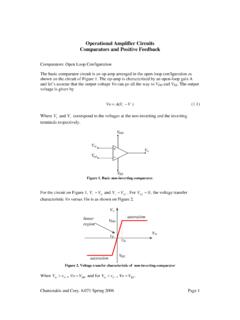
Operational Amplifier Circuits Comparators and Positive ...
ocw.mit.eduOperational Amplifier Circuits Comparators and Positive Feedback Comparators: Open Loop Configuration The basic comparator circuit is an op-amp arranged in the open-loop configuration as shown on the circuit of Figure 1. The op-amp is characterized by an open-loop gain A and let’s assume that the output voltage Vo can go all the way to VDD ...

2. Operational Amplifiers
www.cs.tut.fiTLT-8016 Basic Analog Circuits. 2005/2006. 13. Example 2.2 Amplifier Design. Suppose that we need an amplifier with input resistance of 500 kΩor greater and a voltage gain of -10. The feedback resistors are to be implemented in integrated form and have values of 10 kΩor less to conserve chip area. Choose a suitable circuit configuration and ...

P2N2222A Amplifier Transistors - ON Semiconductor
www.onsemi.comAmplifier Transistors NPN Silicon Features ... SWITCHING TIME EQUIVALENT TEST CIRCUITS Scope rise time < 4 ns *Total shunt capacitance of test jig, connectors, and oscilloscope. +16 V-2 V < 2 ns 0 1.0 to 100 s, DUTY CYCLE ≈ 2.0% 1 k +30 V 200 CS* < 10 pF +16 V-14 V 0 < 20 ns

120-volt, 100-watt, DMOS audio amplifier with mute and …
www.st.comThe circuits dedicated to the switching on and off of the amplifier have been carefully optimized to avoid any kind of uncontrolled audible transient at the output. The sequence that we recommend during the on/off transients is shown in Figure 8. The application of figure 9 shows the possibility of sing only one command for both st-by and

CIRCUITS LABORATORY EXPERIMENT 9 Operational …
classes.engineering.wustl.eduCIRCUITS LABORATORY EXPERIMENT 9 Operational Amplifiers 9.1 INTRODUCTION An operational amplifier ("op amp") is a direct-coupled, differential-input, high- gain voltage amplifier, usually packaged in the form of a small integrated circuit.
Design of an Instrumentation Amplifier
www.egr.msu.eduAn instrumentation amplifier is an integrated circuit (IC) that is used to amplify a signal. This type of amplifier is in the differential amplifier family because it amplifies the difference between two inputs. The importance of an instrumentation amplifier is that it can reduce unwanted noise that is picked up by the circuit.

AD8065/AD8066 (Rev. L) - Analog Devices
www.analog.comof use. The AD8065 is a single amplifier, and the AD8066 is a dual amplifier. These amplifiers are developed in the Analog Devices, Inc. proprietary XFCB process and allow exceptionally low noise operation (7.0 nV/√Hz and 0.6 fA/ √. Hz) as well as very high input impedance. With a wide supply voltage range from 5 V to 24 V, the ability to

IdealOpAmpCircuits - Georgia Institute of Technology
leachlegacy.ece.gatech.eduiv IDEALOPAMPCIRCUITS Figure1.4: (a)CircuitforExample1. (b)CircuitforExample2. (c)CircuitforExample3. Solution. The voltage gain decreases when RL is added because of the voltage drop across RO.By

Basic Electronics
engineering.nyu.edu– a current amplifier. • Transistor is analogous to a faucet. – Turning faucet’s control knob alters the flow rate of water coming out from the faucet. – A small voltage/current applied at transistor’s control lead controls a larger current flow through its other two leads.