Inductance Calculation
Found 12 free book(s)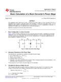
Basic Calculation of a Buck Converter's Power Stage (Rev. B)
www.ti.comselected IC with an inductor with higher inductance if it is still in the recommended range. A higher inductance reduces the ripple current and therefore increases the maximum output current with the selected IC. If the calculated value is above the maximum output current of the application, the maximum switch current in the system is ...
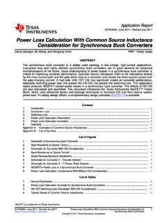
Power Loss Calculation With CSI Consideration for ...
www.ti.comPower Loss Calculation With Common Source Inductance Consideration for Synchronous Buck Converters David Jauregui, Bo Wang, and Rengang Chen..... PMP -Power Stage ABSTRACT The synchronous buck converter is a widely used topology in low-voltage, high-current applications.
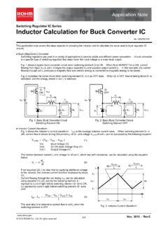
Inductor Calculation for Buck Converter IC
fscdn.rohm.comInductor Calculation of Buck Converter Current-difference between max. and min. (ILP-ILT) is as follows: IN SW D SW IN SW OUT D OUT LP LT V V V L f V V V V V I I (15) Equations (13) and (15) show that large inductance L and high switching frequency will reduce maximum current (ILP)and current difference between max. and min. (ILP-ILT).
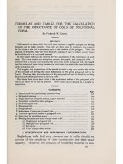
Formulas and tables for the calculation of the inductance ...
nvlpubs.nist.govand thenumberofturnsbeing sameinbothcases,hasnearlythesameinductance as thepolygonal coil. This suggests the presentationof the resultsin sucha way asto enablethe radius

PowerFlex Dynamic Braking Resistor Calculator
literature.rockwellautomation.comWire should be twisted to minimize inductance. Frames 5…6 Wire to the DB resistor should be no longer than 100 feet from the drive terminals. Drive Input Voltage Transistor Turn-On Voltage Maximum Power Calculation Voltage 208 375V DC 395V DC 240 375V DC 395V DC 400 750V DC 790V DC 480 750V DC 790V DC 575 937.5V DC 987V DC 600 937.5V DC 987V DC

Inductance Calculation Techniques --- Part II ...
www.thompsonrd.comInductance calculation references necessarily start with Maxwell’s seminal work [1], first published in 1873. Maxwell worked out some interesting inductance problems, including finding the mutual inductance between circular coaxial filaments [1, pp. 339], and finding the size and shape of a coil which maximizes inductance for a given length of

CHAPTER 12: PRINTED CIRCUIT BOARD (PCB) DESIGN …
www.analog.cominductance 12.21 stray inductance 12.21 mutual inductance 12.22 parasitic effects in inductors 12.24 q or "quality factors" 12.25 don't overlook anything 12.26 stray capacitance 12.27 capacitative noise and faraday shields 12.28 buffering adcs against logic noise 12.29 high circuit impedances are susceptible to noise pickup 12.30

Transformerdesignconsideration forFull Bridge PhaseShift
www.psma.comMar 17, 2020 · LK Inductance A lot of models can be found in literature for calculating the leakage inductance. Two of them are: CLASSICAL MODEL: This is a simple method for calculating the leakage inductance since only a small number of dimensions are necessary related to the winding geometry.

Calculation of Short Circuit Currents
studiecd.dkinductance of a generator. k Correction factor (NF C 15-105) K Correction factor for impedance (IEC 60909). κ Factor for calculation of the peak short-circuit current. Ra Equivalent resistance of the upstream network. RL Line resistance per unit length. Sn Transformer kVA rating. Scc Short-circuit power tmin Minimum dead time for short-circuit

Calculation of PCB Track Impedance
www.polarinstruments.comwhere L is the inductance and C the capacitance per unit length of line. For a stripline, where the electric (and magnetic) fields are in a uniform substrate, dielectric constant εr, equation (9) becomes cC Z r ε 0 = (10) where c is the velocity of light in vacuuo (or free-space). The velocity of pulse travel along the transmission path is r ...

ELECTRICAL POWER TRANSMISSION AND DISTRIBUTION
www.vssut.ac.inWhere L is the inductance in Henry, λ is the flux linkage in Weber-turns and I is the phasor current in Ampere. INDUCTANCE OF SOLID CONDUCTOR DUE TO INTERNAL FLUX Let us consider a solid conductor of radius 'r' cm and the current flowing is 'I' A as shown in Fig.-1.1. o x dx r FIG.-1.1 INTERNAL FLUX LINKAGE OF A ROUND CONDUCTOR.

RF Connector guide - FC Lane
www.fclane.comThe equations for calculation of the electric field and magnetic field are: E = u ln D d × 1 r Electric field E → (volts∕metre) Magnetic field H → (amperes∕metre) H = i 2×π ×1 (1) (2)r D = Inside diameter of outer conductor d=Outerdiameterofinnerconductor u = Voltage between inner and outer conductors (the so-called instantaneous ...