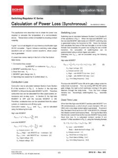
Transcription of Inductor Calculation for Buck Converter IC
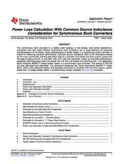
1 1/4 Nov. 2012 - 2012 ROHM Co., Ltd. All rights reserved. Switching Regulator IC Series Inductor Calculation for buck Converter IC This application note covers the steps required in choosing the Inductor and to calculate the value used in buck regulator IC circuits. buck (Step-Down) Converter Switching regulators are used in a variety of applications to provide stable and efficient power conversion. A buck Converter is a specific type of switching regulator that steps down the input voltage to a lower level output. Fig. 1 shows a typical buck Converter circuit when switching element Q1 is ON. When N-ch MOSFET Q1 is ON, current flowing from input VIN to coil L charges the output capacitor CO and supplies output current IO. In this scenario, the current flowing through coil L produces a magnetic field and electric energy is converted to magnetic energy to be stored.
2 Fig. 2 illustrates the same circuit when switching element Q1 is in an OFF state. When Q1 is OFF, free-wheeling diode D1 is activated, and the energy stored in coil L is released. Fig. 1: Basic buck Converter Circuit Fig. 2: Basic buck Converter Circuit Switching Element ON Switching Element OFF Inductor Current Waveform Fig. 3 shows the Inductor s current waveform. IOUT is the average Inductor current value. When switching element Q1 is ON, current flow is shown during ON period tON of Q1, and voltage VL(ON) of coil L can be calculated by the following equation: )VVV(VOUTSWIN)ON(L (1) The relation between current IL and voltage VL of coil L, which has self- inductance , can be calculated using the equation below: dtdILVLL (2) From equation (2), it is clear that by applying additional voltage to the Inductor , the reverse-current direction increases by slope V/L.
3 Current flowing through the coil during tON can be calculated using equation (1), (2), and by the following method; ILT represents current right before switching element Q1 turns ON, ILP represents current right before switching element Q1 turns OFF. LtVVVIIONOUTINSWLTLP (3) The next step is to determine current flow in coil L when the switching element is OFF. VIN: Input Voltage (V) VSW: Q1 ON-state Voltage Drop (V) VOUT: Output Voltage (V) Fig. 3: Inductor Current Waveform VIN CO D1 LRLQ1 VOUTVSW VLON IO VINCO D1L RLQ1 VOUTVL OFFIO VDtONtOFF ILtIOUTILPILT IL dIL=VL(ON)LdtdIL=VL(OFF) Note 2/4 Nov. 2012 - 2012 ROHM Co., Ltd. All rights reserved. Inductor Calculation of buck Converter From Fig. 2, the coil voltage when Q1 in OFF- state is VL(OFF), can be calculated using the following method: OUTD)OFF(LVVV (4) Using equations (2) and (4), the current flowing through coil L when Q1 is OFF is as follows: LtVVIIOFFOUTDLTLP (5) Current flow in the coil L is almost the same as the output current.
4 Consequently, OUTLTLPI2II (6) From equations (3) and (6), ILP during Q1 ON-state is L2tVVVIIONOUTSWINOUTLP (7) Using equations (5) and (6), ILP can be calculated during the period when the switching element is OFF: L2tVVIIOFFOUTDOUTLP (8) On-Duty Calculation On-duty D is the ratio of time the switching element is ON tON versus the switching oscillatory cycle TSW: SWOFFSWONOFFONONSWONft1fttttTtD (9) Using (7), (8), and (9), the duty can be calculated using the expression below: DSWINOUTDVVVVVD (10) By ignoring the voltage drop VSW of the switching element and voltage drop of the diode in equation (10), it is clear that on- duty is fixed by the ratio of output voltage over input voltage: INOUTVVD (11) Maximum Coil Current Value Use equations (9) and (10) to determine tON: SWDSWINOUTDSWONfVVVVVfDt (12) The equation below determines the maximum value of ILP by substituting (12) into (7): SWDSWINOUTDOUTSWINOUTLPfL2 VVVVVVVVII (13) Equation (14) is used to determine the minimum value ILT by substituting (13) into (6): SWDSWINOUTDOUTSWINOUTLTfL2 VVVVVVVVII (14) VD: Forward Voltage Drop across D1 (V) VOUT: Output Voltage (V) Application Note 3/4 Nov.
5 2012 - 2012 ROHM Co., Ltd. All rights reserved. Inductor Calculation of buck Converter Current-difference between max. and min. (ILP ILT) is as follows: SWDSWINOUTDOUTSWINLTLPfLVVVVVVVVII (15) Equations (13) and (15) show that large inductance L and high switching frequency will reduce maximum current (ILP)and current difference between max. and min. (ILP ILT). inductance L Value Calculation Define the ratio of current-difference flowing in coil L (ILP-ILT) versus output current IOUT as current ripple-ratio r . OUTLTLPOUTLIIIIIr (16) Substitute (15) into (16): OUTSWDSWINOUTDOUTSWINILfVVVVVVVVr (17) Then, solve (17) for L to calculate the inductance value: OUTSWDSWINOUTDOUTSWINIrfVVVVVVVVL (H) (18-1) When the output voltage is high, the Calculation can be simplified.
6 OUTSWINOUTOUTINIrfVVVVL (H) (18-2) The Inductor value can be increased to reduce the ripple-ratio; however, this will typically result in an Inductor size that is physically too big for practical use. Consequently, r is usually set between and for buck converters. Maximum Current Flow through the Coil Maximum current flow through the coil can be calculated using the following equation: 2 IrIIOUTOUTL peak (A) or LfV2 VVVISWINOUTINOUTOUT (A) (19) Current flowing through the coil is a combination of output current and ripple-current. When an abnormality occurs (ex. output short) in a transient load condition and there will be a power surge due to the absence of soft-start feature, and it is possible that the actual current flow through the Inductor will exceed the maximum calculated current.
7 Under transient conditions, coil current may increase up to the IC s switching current limit. Therefore, the safest approach is to select an Inductor with a saturation current rating that exceeds the switching current limit, and not the maximum coil current. Effective RMS current flowing through the coil Effective current value of triangular wave can be calculated by the following method. 3 IIIIILTLP2LT2 LPLrms (20) By substituting equations (13) and (14) into (20), we arrive at the following: 2 SWDSWINOUTDOUTSWIN2 OUTL rmsfLVVVVVVVV121II (A) (21) Application Note 4/4 Nov. 2012 - 2012 ROHM Co., Ltd. All rights reserved. Inductor Calculation of buck Converter Example for Coil selection: Determine the operating conditions of the buck Converter : - VIN = 12V Input Voltage - VOUT = Output Voltage - IOUT = 2A Output Current - r = Output Current Ripple Ratio - VSW = ON State Voltage Drop of Switching Element Q1 - VD = * Forward Voltage Drop of Free Wheel Diode - fSW = 380 kHz Switching Frequency * For synchronized rectifier type power conversion, specify ON-state voltage drop of lower side element Q2 (Fig.)
8 4). Calculate the inductance value of the coil by substituting the above parameters into equation (18-1) or (18-2). As per equation (18-1), ( H) As per equation (18-2), ( H) Using equation (19), the maximum current flowing through the coil is as follows: (A) As per equation (21), the effective current value flowing through the coil is (A) Coil selection should be based on the results of the calculations. For this design, 10 H is chosen as the closest standard inductance value. If the selected Inductor value is different from the calculated result, adjust the current ripple value r using equation (17), and substitute the revised value into equation (19) to recalculate the maximum current flowing through the coil. (A) Fig. 4: Basic circuit configuration of a buck Converter using synchronous rectification power conversion.
9 In this example, the upper switching element is in OFF-state. VIN 2012 ROHM Co., Ltd. All rights Customer Support System you for your accessing to ROHM product informations. More detail product informations and catalogs are available, please contact us. Notes No copying or reproduction of this document, in part or in whole, is permitted without the consent of ROHM Co.,Ltd. The content specified herein is subject to change for improvement without notice. The content specified herein is for the purpose of introducing ROHM's products (hereinafter "Products"). If you wish to use any such Product, please be sure to refer to the specifications, which can be obtained from ROHM upon request. Examples of application circuits, circuit constants and any other information contained herein illustrate the standard usage and operations of the Products.
10 The peripheral conditions must be taken into account when designing circuits for mass production. Great care was taken in ensuring the accuracy of the information specified in this document. However, should you incur any damage arising from any inaccuracy or misprint of such information, ROHM shall bear no responsibility for such damage. The technical information specified herein is intended only to show the typical functions of and examples of application circuits for the Products. ROHM does not grant you, explicitly or implicitly, any license to use or exercise intellectual property or other rights held by ROHM and other parties. ROHM shall bear no responsibility whatsoever for any dispute arising from the use of such technical information. The Products specified in this document are intended to be used with general-use electronic equipment or devices (such as audio visual equipment, office-automation equipment, commu-nication devices, electronic appliances and amusement devices).