Transcription of Hysteresis Setting for Comparator - Rohm
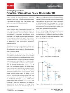
1 1/6 2017 ROHM Co., Ltd. Application Note Comparator Series Hysteresis Setting for Comparator Contents: 1. Circuit configuration and operation 2. Calculation of threshold voltage (resistance division type) 3. Calculation of threshold voltage (reference voltage type) 4. Calculation of threshold voltage (simple type) 5. Comparator output voltage (common) 1. Circuit configuration and operation Hysteresis Comparator A Hysteresis Comparator is operated by applying a positive feedback* to the Comparator . The potential difference between the High and Low output voltages and the feedback resistor are adjusted to change the voltage that is taken as a comparison reference to the input voltage for the +IN terminal.
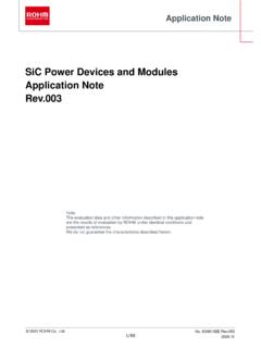
2 The width of variation in the reference voltage is the Hysteresis width. In this circuits the signal is input to the IN terminal ,the output is inverted. VEER3R4 VDVCCR2R1 RpVpFigure 1. Hysteresis Comparator circuit Note: A Comparator cannot be operated as a Hysteresis Comparator when a negative feedback is applied. Pull-up voltage Output Input For open collector/ open drain type Vref 2/6 2017 ROHM Co., Ltd. Application Note Hysteresis Setting for Comparator Operation without Hysteresis When the input signal and Vref (reference voltage) are nearly equal, exceeding the threshold value due to noise or other causes will destabilize the output.
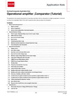
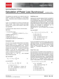
3 (Chattering occurs) Figure 2. is Response waveforms of non- Hysteresis Comparator . (1) When the input signal (-IN) is applied at a voltage sufficiently higher than Vref(+IN), the output is varied according to Vref as a threshold. (2) When the input signal (-IN) is applied at a voltage equivalent to Vref(+IN), the input signal may or may not exceed the threshold at Vref due to noise or other causes, resulting in an instability (chattering). Operation with Hysteresis Since a margin is provided between the High-to-Low and Low-to-High thresholds, no chattering occurs in the output even when a signal is input at a voltage near the threshold voltages.
4 Figure 3. is Response waveforms of Hysteresis Comparator . (3) When the input signal (-IN) is applied at a voltage sufficiently higher than VthH(+IN) and VthL(+IN), the output is varied according to Vref as a threshold. (4) When the input signal (-IN) is applied at a voltage equivalent to VthH(+IN) or above, no chattering occurs since the output will not respond unless the input falls below the threshold at VthL(+IN). VthL is the voltage switching from Low to High. VthH is the voltage switching from High to Low. Figure 2. Response waveforms of non- Hysteresis Comparator Figure 3.
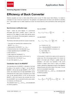
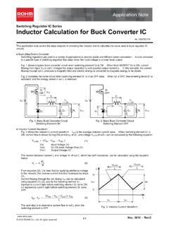
5 Response waveforms of Hysteresis Comparator (3) (4) VCC VEE(GND) VthH(+IN) VthL(+IN) Vin(-IN) VCC VEE(GND) VthH(+IN) VthL(+IN) Vp VCC VEE(GND) VthH(+IN) VthL(+IN) Vin(-IN) VCC VEE(GND) VthH(+IN) VthL(+IN) Vp Input Input Output Output (Vp: pull-up voltage) (1) (2) VCC VEE(GND) Vref(+IN) Vin(-IN) Input Output VCC VEE(GND) Vref(+IN) Vout(OUT) Input Output Vp 3/6 2017 ROHM Co., Ltd. Application Note Hysteresis Setting for Comparator )(112211312 RaRRRRVRRaRVVDOHthH )(112211312 RaRRRRVRRaRVVDOLthL thLthHthVVV 2. Calculation of threshold voltage (resistance division type) Derivation of threshold voltage for Hysteresis Comparator Calculation process Form a current equation for Vref and VD in Figure 4.
6 Solve equation (2) for Vout. Solve equation (1) for Vref. Figure 4. Hysteresis Comparator circuit using resistance division Hysteresis width In the circuit configuration shown here, the threshold voltages and the Hysteresis width are expressed as follows. where )111(1431 RRRa Threshold voltages ..(1) ..(2) ..(3) ..(4) where +-R1R2R3R4 Vref VD VEEVCCRpVp Point The calculation of the threshold voltages is complicated since it involves many parameters. We suggest inputting the equations in advance with software such as a spreadsheet program to perform the calculation.
7 Pull-up voltage Output Input 21413 RVVRVVRVRVVRVV outrefrefrefrefD refoutoutrefVRRVRRVVVVRRVRR12121212)1( 1343141133)111(RVRVVRRRRVRVRVRVRVD refrefrefrefD 14313431)111(1)111(1 RVRRRRVRRRVDref VRaVRaVDref13 )111(1431 RRRa Vout 4/6 2017 ROHM Co., Ltd. Application Note Hysteresis Setting for Comparator +-R1R2 Vref VCCRpVp VEEOH refthHaVVRRaV 12 OLrefthLaVVRRaV 12thLthHthVVV Solving equations (3) and (4) for V allows equation (5) to be obtained. V provides two threshold voltages for the Hysteresis Comparator : VthL is the voltage switching from Low to High and VthH is the voltage switching from High to Low.
8 Vout is the output voltage of the Comparator providing two values: VOH is the High output voltage and VOL is the Low output voltage. 3. Calculation of threshold voltage (reference voltage type) Calculation of threshold voltages for a Hysteresis Comparator when a reference voltage is provided from a power source or other supplies. Form a current equation for Vref and V. Substitute the coefficient of V with 1/a and solve equation (2) for V Since Vout takes two values, the high level output voltage VOH and the low level output voltage VOL, the threshold voltages VthL and VthH can be expressed as in equation (3).
9 (5) VRRVVRR outref)1(1212 Vout 1211 RRa Figure 5. Hysteresis Comparator circuit using Vref reference power source outrefaVVRRaV 12 Threshold voltages Hysteresis width 1211 RRa Point Since there are fewer variables involved in determining the threshold compared with the calculation for the resistance division type, the design flexibility is reduced for the voltage Setting ..(1) 21 RVVRVV outref ..(2) ..(3) Input Output Pull-up voltage )(112211312 RaRRRRVRRaRVVDout outrefVVVRRVRR 1212 5/6 2017 ROHM Co., Ltd. Application Note Hysteresis Setting for Comparator +-R1R2R3 VEEVCCRpVp VrefthLthHthVVV 4.
10 Calculation of threshold voltage (simple type) Calculation formula for the Hysteresis of the simple type Hysteresis Comparator Form a current equation for V. Substitute the coefficient of V with 1/a and solve equation (2) for V. 01111133211 VRVoRVRVRVRrefVoRVRVRRRref3132111)111( )11()111(131321 VoRVRRRRVref 0321 RVVRVRVVOrefOHrefthHVRaVRaV31 OLrefthLVRaVRaV31 Figure 6. Simple type Hysteresis Comparator Threshold voltages Hysteresis width ..(1) ..(2) Point As there is no input resistance, the design flexibility is reduced for the Setting width of the threshold.