Intake manifold
Found 9 free book(s)
5.4 LITER FORD INTAKE MANIFOLD INSTALLATION …
www.jegs.comdamage to the intake manifold and to the engine! 1. Carefully remove intake manifold per the service procedure outlined in shop manual. 2. Clean all mounting surfaces. 3. Reinstall intake manifold per shop manual. 4. Tighten intake bolts as follows: Stage One: 2 Nm (18 in-lbs) Stage Two: 25 Nm (18 ft-lbs) 5. Install intake bolts in sequence ...

302/351W Intake Manifold INSTALLATION INSTRUCTIONS
performanceparts.ford.comand intake manifold. The use of the wrong gasket can result in vacuum and coolant leaks. Intake gasket M-9439-A50 fits Ford Racing "X" and "Z" series cylinder heads. NOTE : Due to the wide variety of small-block Ford cylinder heads and intake manifolds, it is mandatory to verify the fitment of the intake manifold to cylinder heads.

2011-2019 5.0L Coyote Improvements - Ford Motor Company
performanceparts.ford.comIntake manifold: The Gen 2 intake manifold will fit Gen 1 engine, however no appreciable performance gains have been found • The Gen 2 intake now has CMCV (charge motion control valves) for emissions and low speed idle quality • Gen 1 intake manifolds can be used on the Gen 2 heads/engine with minor modifications to the manifold shown

Fastener Specifications - Pace Performance
paceperformance.comFeb 16, 2017 · Intake Manifold Bolt • First Pass in Sequence 5Y (44lbin) • Final Pass in Sequence 10Y (89lbin) Intake Manifold Cover Bolt 4.5Y (40lbin) Intake Manifold Cover Stud 4.5Y (40lbin) Jumper Harness Bolt 25Y (18lbft) Knock Sensor Bolt 25Y (18lbft) Knock Sensor Heat Shield Bolt 25Y (18lbft) Low Pressure Fuel Feed Pipe to Rocker Arm Cover Bolt

QUICK FUEL TECHNOLOGY®
documents.holley.comSep 11, 2019 · then it should be routed to another vacuum connection in the intake manifold. This connection should be to the plenum of the intake manifold, not an individual intake runner. Vacuum connections to the new carburetor as shown below: NOTE: Vacuum tubes available on gas carburetors only, not on blower, blow-through, alcohol, or E85 carburetors.

100-002 Engine Diagrams - JustAnswer
ww2.justanswer.comNov 06, 2010 · 3. Intake manifold temperature sensor 4. Intake manifold pressure sensor 5. Aftercooler seawater outlet 6. Air cleaner or filter 7. Aftercooler air inlet 8. Aftercooler housing 9. SAE number 1 flywheel housing 10. Crankshaft speed sensor 11. Oil pressure sensor 12. Aftercooler seawater inlet 13. Engine control module (ECM) 14. Fuel lift pump ...

CARBURETOR
documents.holley.comIf the intake manifold is being changed at this time, install the new manifold according to the manifold’s manufacturer’s directions. Since we are not familiar with all manifold instructions, Holley® cannot accept responsibility for their validity. INSTALLATION: 1. Install the carburetor-mounting studs (not provided) in the proper location ...
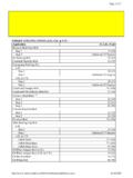
TORQUE SPECIFICATIONS - JustAnswer
ww2.justanswer.comJun 14, 2009 · Intake Manifold Upper (4.3) Step 1 44 (5) Step 2 88 (10) Upper (5.0 & 5.7) Step 1 44 (5) Step 2 88 (10) Lower(3) Step 1 27 (3) Step 2 106 (12) Step 3 133 (15) Oil Pan Front & Rear Stud (5.7L) 106 (12) Oil Pump Cover Bolt 106 (12) Rear Crankshaft Oil Seal Retainer Bolt 106 (12) Valve Cover Bolt 106 (12) (1) Apply GM Sealant (1052080) to head ...

Manifold Pressure Sucks! - Advanced Pilot
www.advancedpilot.comManifold Pressure Sucks! First appeared March 21, 1999, www.avweb.com If you fly behind a piston engine with a controllable-pitch propeller, the manifold pressure gauge plays an important part in the power settings you use. Few pilots, however, have any real understanding of what the instrument actually measures or what its readings truly signify.