Search results with tag "Intake manifold"

5.4 LITER FORD INTAKE MANIFOLD INSTALLATION …
www.jegs.comdamage to the intake manifold and to the engine! 1. Carefully remove intake manifold per the service procedure outlined in shop manual. 2. Clean all mounting surfaces. 3. Reinstall intake manifold per shop manual. 4. Tighten intake bolts as follows: Stage One: 2 Nm (18 in-lbs) Stage Two: 25 Nm (18 ft-lbs) 5. Install intake bolts in sequence ...

302/351W Intake Manifold INSTALLATION INSTRUCTIONS
performanceparts.ford.comand intake manifold. The use of the wrong gasket can result in vacuum and coolant leaks. Intake gasket M-9439-A50 fits Ford Racing "X" and "Z" series cylinder heads. NOTE : Due to the wide variety of small-block Ford cylinder heads and intake manifolds, it is mandatory to verify the fitment of the intake manifold to cylinder heads.

WEIAND SUPERCHARGER INSTALLATION INSTRUCTIONS …
documents.holley.comthe intake runners and the exterior of the manifold. Note: It may be necessary to drill and tap the hole in the manifold for the boost gauge, if desired, before installing the manifold on the engine. STEP 10 WEIAND does not include intake manifold gaskets in the kit, but recommends that you use a Fel-Pro intake manifold gasket set as follows:

2011-2019 5.0L Coyote Improvements - Ford Motor Company
performanceparts.ford.comIntake manifold: The Gen 2 intake manifold will fit Gen 1 engine, however no appreciable performance gains have been found • The Gen 2 intake now has CMCV (charge motion control valves) for emissions and low speed idle quality • Gen 1 intake manifolds can be used on the Gen 2 heads/engine with minor modifications to the manifold shown

Edelbrock 27011 Intake Manifold Installation Instructions
www.jegs.comINSTALLATION INSTRUCTIONS 1) Use either Edelbrock #7201 or Fel-Pro #1256 (#1205 for aftermarket heads) intake gasket set when installing this intake manifold. 2) Fully clean the cylinder head intake flanges and the engine block end seal surfaces.

Fastener Specifications - Pace Performance
paceperformance.comFeb 16, 2017 · Intake Manifold Bolt • First Pass in Sequence 5Y (44lbin) • Final Pass in Sequence 10Y (89lbin) Intake Manifold Cover Bolt 4.5Y (40lbin) Intake Manifold Cover Stud 4.5Y (40lbin) Jumper Harness Bolt 25Y (18lbft) Knock Sensor Bolt 25Y (18lbft) Knock Sensor Heat Shield Bolt 25Y (18lbft) Low Pressure Fuel Feed Pipe to Rocker Arm Cover Bolt

The Audi 1.8L and 2.0L Third Generation EA888 Engines
static.nhtsa.govIntake manifold flaps yes Intake camshaft adjustment - continuous yes Exhaust camshaft adjustment - continuous no High pressure injectors (FSI) yes Injectors in the intake manifold (MPI) no Secondary air system yes Audi valvelift system - for exhaust valves no Rotary slide valve yes Regulated oil pump yes Tumble flaps yes Technical features 1 ...

CARBURETOR
documents.holley.comIf the intake manifold is being changed at this time, install the new manifold according to the manifold’s manufacturer’s directions. Since we are not familiar with all manifold instructions, Holley® cannot accept responsibility for their validity. INSTALLATION: 1. Install the carburetor-mounting studs (not provided) in the proper location ...

QUICK FUEL TECHNOLOGY®
documents.holley.comSep 11, 2019 · then it should be routed to another vacuum connection in the intake manifold. This connection should be to the plenum of the intake manifold, not an individual intake runner. Vacuum connections to the new carburetor as shown below: NOTE: Vacuum tubes available on gas carburetors only, not on blower, blow-through, alcohol, or E85 carburetors.

Service Manual: 3.6L ENGINE - SERVICE INFORMATION …
f01.justanswer.comFig 11: Left Intake Manifold Support Brackets & Retaining Bolts Courtesy of CHRYSLER GROUP, LLC 19.Remove the bolts (2) and remove the LH upper intake manifold support brackets (1). ... Do not lay the cylinder head on its gasket sealing surface, due to the design of the cylinder head gasket, any distortion to the cylinder head sealing surface ...

100-002 Engine Diagrams - JustAnswer
ww2.justanswer.comNov 06, 2010 · 3. Intake manifold temperature sensor 4. Intake manifold pressure sensor 5. Aftercooler seawater outlet 6. Air cleaner or filter 7. Aftercooler air inlet 8. Aftercooler housing 9. SAE number 1 flywheel housing 10. Crankshaft speed sensor 11. Oil pressure sensor 12. Aftercooler seawater inlet 13. Engine control module (ECM) 14. Fuel lift pump ...

CARBURETOR - Holley
documents.holley.comIf the intake manifold is being changed at this time, install the new manifold according to the manifold’s manufacturer’s directions. ... Place the air cleaner gasket (supplied) on the sealing flange, and install the air cleaner. 15. With some air cleaner configurations, it may be necessary to use an air cleaner spacer to provide adequate ...
ENGINE Workshop Manual 4M41
mitsubishilinks.comIntake manifold Boost air temperature sensor 15 – 1 Gas filter assembly 17 – 1 Turbocharger assembly Eye bolt (for oil pipe) 20 – 2 Eye bolt (for water pipe) 25 – 2 Coupler nut 49 – 4 Turbocharger nut 49 – 4 Turbocharger bolt 54 – 5 Exhaust manifold Exhaust manifold nut 30 – 3 Injection pump assembly Injection pipe 25 – 2
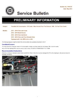
Bulletin No.: PIP5197 Date: May-2014 Subject: Possible Oil ...
static.nhtsa.govIf the intake manifold Non Return Valve is seated properly, then perform the following. Perform PI0552 to check the engine oil dipstick and oil fill cap for proper sealing. Perform PIP4925 to check for any air leaks to the intake system. Record the crankcase pressure.
LS Series 19171935 - Chevrolet
www.chevrolet.comBooster is a plug in the rear of the intake manifold. If you need the vacuum source for your brake system the plug needs to be removed and you will need fitting #12559760 available from any GM dealer. Oil Pressure Sensor: If your harness connector does not fit your oil pressure sensor you can purchase sensor p/n 12616646 or equivalent.

Service Bulletin Date: April, 2012
static.nhtsa.govREPLACE it with a new throttle body assembly. 4. Remove the throttle body and discard the throttle ... sensor cover and carefully lift it up and separate it from the throttle body. 2697650 Notice: DO NOTallow the intermediate ... Install a NEW throttle body gasket to the intake manifold. 25. Install the throttle body, bolts and nuts. DO NOT ...

Circle Track Crate Engine Technical Manual
staffordmotorspeedway.comThe 8 bolt locations are: 2 bolts in the intake manifold, 2 bolts in the front cover, 2 bolts in the oil pan & one bolt in each cylinder head.. The valve covers are not sealed as it is important to properly lash the valves. (See valve lash procedure on page 9)
TORQUE SPECIFICATIONS - JustAnswer
ww2.justanswer.comJun 14, 2009 · Intake Manifold Upper (4.3) Step 1 44 (5) Step 2 88 (10) Upper (5.0 & 5.7) Step 1 44 (5) Step 2 88 (10) Lower(3) Step 1 27 (3) Step 2 106 (12) Step 3 133 (15) Oil Pan Front & Rear Stud (5.7L) 106 (12) Oil Pump Cover Bolt 106 (12) Rear Crankshaft Oil Seal Retainer Bolt 106 (12) Valve Cover Bolt 106 (12) (1) Apply GM Sealant (1052080) to head ...
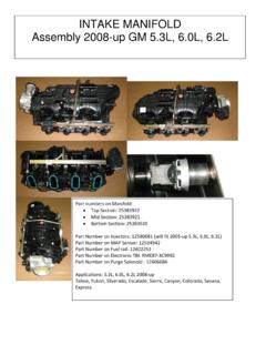
INTAKE MANIFOLD Assembly 2008-up GM 5.3L, 6.0L, 6
www.surplusparts.comINTAKE MANIFOLD . Assembly 2008-up GM 5.3L, 6.0L, 6.2L. Part numbers on Manifold: • Top Section: 25383922 • Mid Section: 25383921 • Bottom Section: 25383920
Similar queries
Intake Manifold, Intake, 351W Intake Manifold INSTALLATION INSTRUCTIONS, SUPERCHARGER, Manifold, Edelbrock 27011 Intake Manifold Installation Instructions, INSTALLATION INSTRUCTIONS, Edelbrock, And 2.0L Third Generation EA888 Engines, Holley, QUICK FUEL, Sealing, 100-002 Engine Diagrams, Chevrolet, Service Bulletin Date: April, 2012, Assembly, Circle Track Crate Engine Technical Manual, INTAKE MANIFOLD Assembly 2008-up, INTAKE MANIFOLD . Assembly 2008-up