Of Transmission Design
Found 7 free book(s)MT-094: Microstrip and Stripline Design - Analog Devices
www.analog.comMicrostrip and Stripline Design . INTRODUCTION . Much has been written about terminating PCB traces in their characteristic impedance, to avoid signal reflections. However, it may not be clear when transmission line techniques are appropriate. A good guideline to determine when the transmission line approach is necessary for logic signals
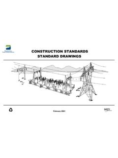
CONSTRUCTION STANDARDS STANDARD DRAWINGS - WAPA
www.wapa.gov114. 41 6157 – Standard Design Transmission Lines Type 3TD 115Kv 3-pole Tension Dead End Structure 115. 41 9002 Rev. N – Transmission Line Standards Barbed Wire Gate For Right -of-Way Fences 116. 41 9003 Rev. C – Transmission Line Standards Electric Barbed Wire Gate For Right -of-Way Fences
Differential Impedance …finally made simple
ewh.ieee.org• The instantaneous impedance of the transmission line • The Characteristic impedance of the transmission line Just referring to “…the impedance” may be a bit ambiguous Eric Bogatin 2000 Slide -10 www.BogatinEnterprises.com MYTHS Training for Signal Integrity and Interconnect Design Return Path in T Lines Current into signal line
17: Transmission Lines - Imperial College London
www.ee.ic.ac.ukA transmission line is a wire with a uniform goemetry along its length: the capacitance and inductance of any segment is proportional to its length. We represent as a large number of small inductors and capacitors spaced along the line. The signal speed along a transmisison line is …
Topic 1: Basics of Power Systems
intra.ece.ucr.eduTransmission Line Admittance Dr. Hamed Mohsenian-Rad Communications and Control in Smart Grid Texas Tech University 17 • For the transmission line connecting bus ito bus k: Addmitance: y ik Example: y ik = 1 –j 4 (per unit) Note that, y ii is denoted by y i and indicates:
Matching Networks - University of California, Berkeley
rfic.eecs.berkeley.edu\RF design is all about impedance matching." Inductors and capacitors are handy elements at impedance matching. Viewed as a black-box, an impedance matcher changes a given load resistance R L to a source resistance R S. Without loss of generality, assume R S > R L, and a power match factor of m = R S=R L is desired. In fact any matching network ...
Wastewater Technology Fact Sheet: Ultraviolet Disinfection
www3.epa.govFact sheet that describes ultraviolet disinfection as a wastewater treatment system. Provides information on technologies, advantages and disadvantages, design criteria, operation and maintenance, and costs. Also available in Spanish (EPA 832-F-99-064). Keywords


