Power Switching
Found 9 free book(s)
Power Semiconductor Switching Devices
www.egr.unlv.edu• It is the fastest power switching device with switching frequency more than 1 MHz, with voltage power ratings up to 1 kV and current rating as high as 300 A. • On-state requires continuous application of gate-source voltage of appropriate magnitude.
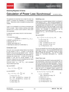
Calculation of Power Loss (Synchronous) : Power Management
fscdn.rohm.comSwitching Regulator IC Series Calculation of Power Loss (Synchronous) This application note describes how to obtain the power loss required to calculate the temperature of a semiconductor device. Temperature control is important to ensuring product reliability. Figure 1 is a circuit diagram of a synchronous rectification type DC/DC converter.

UniFi PoE Switch Datasheet - Ubiquiti
dl.ubnt.comSwitching Capacity 36 Gbps Forwarding Rate 26.78 Mpps MAC Address Table 16384 Maximum Aggregations 6 Monitoring Sessions 1 Maximum VLANs 255 Power Method 100-240VAC/50-60 Hz, Universal Input Power Supply AC/DC, Internal, 150W DC Max. Power Consumption Including PoE Output Excluding PoE Output 150W 28W LEDs Per Port RJ45 Data Ports SFP Data Ports

Snubber Circuits Suppress Voltage Transient Spikes in ...
pdfserv.maximintegrated.comoutput power supplies with high output voltage for power levels up to 100W. Flyback topologies store and transfer energy using a transformer, which due to physical limitations can cause large voltage transient spikes during the switching cycle. This article outlines the design of …

Basic Calculation of a Buck Converter's Power Stage (Rev. B)
www.ti.comnecessary to stabilize the input voltage due to the peak current requirement of a switching power supply. The best practice is to use low-equivalent series resistance (ESR) ceramic capacitors. The dielectric material must be X5R or better. Otherwise, the capacitor loses much of its capacitance due to dc bias or temperature.

Power Supply Circuits - solo electronica
www.soloelectronica.netThe switching power supply continues to increase in popularity and is one of the fastest growing markets in the world of power conversion. They offer the designer several important advantages over linear series–pass regulators. These advantages include significant advancements in the areas of size and weight reduction, improved efficiency, and
Topic 1: Basics of Power Systems
intra.ece.ucr.eduPower Flow Equations Dr. Hamed Mohsenian-Rad Communications and Control in Smart Grid Texas Tech University 27 • Given the power injection values at all buses, we can use to obtain the voltage angles at all buses. • Let P ij denote the power flow from bus ito bus j, we have: N j P k B kj k j 1 ( ) P ij B ij (

Power MOSFET - Vishay Intertechnology
www.vishay.comThird generation Power MOSFETs from Vishay provide the designer with the best combination of fast switching, ruggedized device design, low on-resistance and cost-effectiveness. The TO-247 package is preferred for commercial-industrial applications where higher power levels preclude the use of TO-220 devices. The TO-247 is similar but superior ...

Power MOSFET Basics - Understanding Voltage Ratings
www.mouser.comswitching (UIS). The standard UIS circuit and simplified waveforms are shown in Figures 2a and 2b. Though overvoltage and avalanche breakdown are evident, it should be noted that the UIS is a current-driven, transient event. The avalanche current in this case is the same as the peak inductor current indicated by the red dashed line in Figure 1b.