Transcription of Calculation of Power Loss (Synchronous) : Power Management
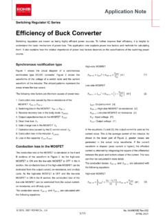
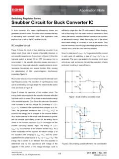
1 1/3 - Rev. 003 2016 ROHM Co., Ltd. All rights reserved. switching Regulator IC Series Calculation of Power loss (Synchronous) This application note describes how to obtain the Power loss required to calculate the temperature of a semiconductor device. Temperature control is important to ensuring product reliability. Figure 1 is a circuit diagram of a synchronous rectification type DC/DC converter. Figure 2 shows a switching node voltage waveform and an inductor current waveform, where Power loss is generated. IC Power loss comes mainly in the form of the five factors listed below. 1. Conduction loss caused by MOSFET on-resistance , 2. MOSFET switching loss 3. Dead time loss 4. MOSFET gate charge loss 5. Operating loss caused by IC control circuit Conduction loss Conduction loss is calculated between Section A and Section B of the waveform in Fig.
2 2. In Section A, the high-side MOSFET is ON and the low-side MOSFET is OFF. Therefore, conduction loss can be calculated from the output current, on-resistance and on-duty cycle. In Section B, the high-side MOSFET is OFF and the low-side MOSFET is ON. Therefore, conduction loss can be calculated from the output current, on-resistance and off-duty cycle. Conduction losses and can be calculated using the following formulas. High-side MOSFET Low-side MOSFET 1 :Output current : High side MOSFET on resistance : Low side MOSFET on resistance : Input voltage :Output voltage switching loss switching loss is calculated between Section C and Section D of the waveform in Fig. 2. When the high-side MOSFET and the low-side MOSFET alternately turn ON/OFF, switching - loss is generated during the transition to ON.
3 Since the formula that calculates the areas of the two triangles is similar to the formula that calculates the Power loss during the rise and fall transition, the Calculation of switching - loss can be approximated using a simple figure Calculation . switching loss can be calculated using the following formula. High-side MOSFET 12 :Input voltage :Output current :High side MOSFET rise time :High side MOSFET fall time : switching frequency The low-side MOSFET turns ON at the gate voltage while the body-diode is powered. Then, by turning OFF the FET at the gate voltage, the load current continues running in the same direction through the body-diode. Thus, the drain voltage remains low. Accordingly, switching - loss becomes minimal. Dead Time loss When both the high-side MOSFET and low-side MOSFET turn ON simultaneously, a short-circuit occurs between VIN and GND, and a very large current spike is generated.
4 To prevent this, the dead time is set to turn OFF both MOSFETs, although the inductor current continuously flows. During the dead time, this inductor current flows to the low-side MOSFET body-diode. Dead time loss is calculated between section E and section F of the waveform in Fig. 2, using the following formula. : Low side MOSFET Body diode forward voltage :Output current : Dead time at rising : Dead time at falling : switching frequency (1)(2)(3)(4) Note 2/3 - Rev. 003 2016 ROHM Co., Ltd. All rights reserved. Calculation of Power loss Synchronous Rectification Type Gate Charge loss Gate charge loss is a Power loss ascribed to MOSFET gate charging. It depends on the gate electric charge (or the gate capacity) of the high-side MOSFET and low-side MOSFET. Gate charge loss is calculated using the following formula.
5 Or :High side MOSFET gate electric charge :Low side MOSFET gate electric charge :High side MOSFET gate capacity :Low side MOSFET gate capacity :Gate drive voltage : switching frequeny IC Operating loss Consumption Power in the IC control circuit is calculated using the following formula. :Input voltage : IC consumption current Total Power loss IC Power loss P is the total of all these values. P :Conduction loss high side :Conduction loss low side : switching loss high side :Dead time loss :Gate charge loss :IC operating loss DCGS LSGDSGCGS HControllerICCVINHigh side MOSFETRON HLow side MOSFETRON LBody DiodeVDRLVOIOILVSWFB Figure 1. Synchronous Rectification Type DC/DC Converter Circuit (5)(6)(7)(8)Application Note 3/3 - Rev.
6 003 2016 ROHM Co., Ltd. All rights reserved. Calculation of Power loss Synchronous Rectification Type trtftONtOFFtDftDrVINVSW0 ILtRON H IORON L IO Figure 2. switching Waveform and loss Calculation Example Formula Parameter Result 1. Conduction loss 1 :Inputvoltage 12 :Outputvoltage :Output current :High side MOSFET on resistance 100 :Low side MOSFET on resistance 70 : switching frequency :High side MOSFET rise time 4 :High side MOSFET rise time 6 :Low side MOSFET body diode forward voltage :Dead time in rising 30 :Dead time in falling 30 :High side MOSFET gate electric charge 1 :Low side MOSFET gate electric charge 1 :High side MOSFET gate capacity 200 :Low side MOSFET gate capacity 200 :Gate drive voltage :IC consumption current 375 2.
7 switching loss 12 360 3. Dead time loss 180 4. Gate charge loss 20 5. IC operating loss 12 Total Power loss P IC internal parameters such as MOSFET gate capacity and body-diode forward voltage are not open to the public in many cases. Even in such a case, it is possible to make an estimate by using the values in the above Calculation example. 2016 ROHM Co., Ltd. All rights Customer Support System you for your accessing to ROHM product informations. More detail product informations and catalogs are available, please contact us. Notes The information contained herein is subject to change without notice. Before you use our Products, please contact our sales representative and verify the latest specifica-tions :Although ROHM is continuously working to improve product reliability and quality, semicon-ductors can break down and malfunction due to various , in order to prevent personal injury or fire arising from failure, please take safety measures such as complying with the derating characteristics, implementing redundant and fire prevention designs, and utilizing backups and fail-safe procedures.
8 ROHM shall have no responsibility for any damages arising out of the use of our Poducts beyond the rating specified by of application circuits, circuit constants and any other information contained herein are provided only to illustrate the standard usage and operations of the Products. The peripheral conditions must be taken into account when designing circuits for mass technical information specified herein is intended only to show the typical functions of and examples of application circuits for the Products. ROHM does not grant you, explicitly or implicitly, any license to use or exercise intellectual property or other rights held by ROHM or any other parties. ROHM shall have no responsibility whatsoever for any dispute arising out of the use of such technical Products are intended for use in general electronic equipment ( AV/OA devices, communi-cation, consumer systems, gaming/entertainment sets) as well as the applications indicated in this Products specified in this document are not designed to be radiation use of our Products in applications requiring a high degree of reliability (as exemplified below), please contact and consult with a ROHM representative.
9 Transportation equipment ( cars, ships, trains), primary communication equipment, traffic lights, fire/crime prevention, safety equipment, medical systems, servers, solar cells, and Power transmission not use our Products in applications requiring extremely high reliability, such as aerospace equipment, nuclear Power control systems, and submarine shall have no responsibility for any damages or injury arising from non-compliance with the recommended usage conditions and specifications contained has used reasonable care to ensure the accuracy of the information contained in this document. However, ROHM does not warrants that such information is error-free, and ROHM shall have no responsibility for any damages arising from any inaccuracy or misprint of such use the Products in accordance with any applicable environmental laws and regulations, such as the RoHS Directive.
10 For more details, including RoHS compatibility, please contact a ROHM sales office. ROHM shall have no responsibility for any damages or losses resulting non-compliance with any applicable laws or providing our Products and technologies contained in this document to other countries, you must abide by the procedures and provisions stipulated in all applicable export laws and regulations, including without limitation the US Export Administration Regulations and the Foreign Exchange and Foreign Trade document, in part or in whole, may not be reprinted or reproduced without prior consent of ) 2)3)4)5)6)7)8)9)10)11)12)13)14)