Transcription of 06-GB Moment Connections - cvut.cz
1 466 Moment Connections Moment Connections are designed to transfer bending moments, shear forces and sometimes normal forces. The design strength and stiffness of a Moment connection are defined in relation to the strength and stiffness of the connected members. The design strength of a Moment connection may be full- strength ( the Moment capacity of the connection is equal to or large than the capacity of the connected member) or partial-strength ( the Moment capacity of the connection is less than that of the connected member). Similarly the stiffness of a Moment connection can be rigid or semi-rigid compared to the stiffness of the connected member. The rotation capacity of the structure may be provided by either the connection or the connected member.
2 Development of the component method In the past Connections were designed as either pinned or rigid, full strength Connections . Considerable work on connection behaviour has been completed and the concepts of semi-rigid design and partial strength design have been developed, which model more accurately the true behaviour of Connections . These models have been developed into a comprehensive set of design rules which have been introduced into Eurocode 3 part [prEN 1993-1-8, 2003]. These rules allow the designer to calculate the strength, stiffness and deformation capacity of Moment Connections . The following steps are required to design a Moment connection: Determine the path of the forces through the connection.
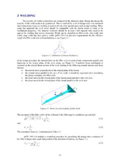
3 The tensile force in the top flange of the beam shown in Figure must pass through the fillet welds of the connected end plate, the end plate in bending, the bolts in tension, the column flange in bending, the column web in tension, the column web in shear and the column web in compression, in order to balance the compression force coming from the beam compression flange. Furthermore the path of other forces ( the shear force from the beam ) has to be determined in a logical way. Of course the forces in the connection must be in equilibrium with the applied bending Moment , shear force and /or the normal force acting on the connection. Once the path of the forces is determined, the strength of every part or component of the connection in this path must be calculated.
4 The component in the chain with the lowest strength governs the strength of the connection ( the tensile force in the top beam flange). The stiffness of the connection depends on the deformations of the components in the path that the forces follow. The deformation of each component gives the stiffness of the connection. The third important mechanical property of a connection is its deformation capacity. Deformation capacity is usually provided by plastic deformation of one or more components. If the strength of the connection clearly exceeds the strength of one of the connected members, the designer can rely on the deformation capacity coming from the connected member, the formation of a plastic hinge in the beam .
5 After the mechanical properties of all components have been determined, the various components can be assembled to determine the strength, stiffness and deformation capacity of the whole connection. The above method for the determination of the mechanical properties of the connection is called the component method. Rules for calculating the strength, stiffness and deformation capacity of each component are given in prEN 1993-1-8. The principles of the component method are based on Zoetemeijer s work [Zoetemeijer, 1983b]. Later, other researchers worked on this method to determine the mechanical properties of more components and to refine the calculation methods, in order to obtain more accuracy in the description of the mechanical behaviour.
6 Furthermore many tests were carried out to validate many different connection configurations. For further study see the references at the end of this publication. The accuracy of the component method depends on the accuracy of the description of the basic components and on the quality of the assembling process. It is assumed that the component properties are independent. However, some components do not act independently, but influence others. For hand calculation this can only be accounted for in a simplified way, because the general approach results in a complicate iterative calculation procedure. This is not a problem for software. An example of the components for a bolted beam to column connection is given in Figure 47 cedfgiunstiffened column web in shearunstiffened column web in compressionbeam flange in compressioncolumn flange in bendingbolt row in tensionhend plate in bendingunstiffened column web in tensionfgifgihhdedec Figure Components represented by springs in a bolted beam to column joint Practical application of the component method The component method allows the designer to analyse many different connection configurations.
7 It enables the design of more economical Connections than the traditional design methods based on tables (that could only be used for a limited number of connection configurations). The component method is complex and requires considerable effort even for the simplest Moment connection. For practical application, therefore several computer programs have been developed, which can quickly determine a connection s mechanical properties. These computer programs can also be used to examine the effects that small changes have on a connection s strength, stiffness and deformation capacity. It is noted, however, that before using such programs, the designer must check that the software has been validated.
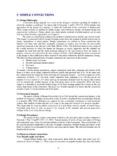
8 Determination of the connection s strength, stiffness and rotational capacity As indicated above, the properties needed for the global analysis of a structure are the bending Moment strength (resistance) Mj,Rd, the deformation / rotational stiffness Sj and the deformation / rotational capacity Cd. Figure gives an example of a beam to column connection and its Moment rotational diagram. In tests, the first part of the Moment rotational diagram (representing the stiffness), is usually linear. However, the linear elastic curve deviates from its straight line at low bending moments [Wald, Steenhuis, 1993]. This is due to local plasticity caused by stress concentrations and residual stresses. In prEN1993-1-8 it is assumed that up to 2/3 of the calculated Moment resistance the behaviour is elastic, following the straight line determined by the calculated (initial) stiffness.
9 After reaching 2/3 of the Moment resistance, the stiffness is reduced until the Moment resistance Mj,Rd is reached. Rules are given in prEN1993-1-8, see also the question 6Q&A1. Componenet - web panel in shearConnectionComponents in tensionComponent - column web in tensionComponent - olumn web in compressionComponents in compression Design curveJoint resistance Mj,RdDeformation capacity j,CdInitial stiffness Sj,ini Elastic 2/3 Mj,Rd limit Experimental curveRotation, , mradM, Moment , kNmShape by stiffness ratio factorJoint Figure Basic components of a beam to column joint and the resulting Moment rotational diagram 48 The required deformation capacity (rotational capacity) of a joint depends on the type of the structure ( statically determined or statically indeterminate) and the method of global analysis for the whole structure (elastic or plastic)
10 , but seldom this exceeds 60 mrad, see Figure The determination of the rotational capacity is qualitative. In prEN1993-1-8, deemed to satisfy rules are given, if yielding of the column flange or end plate in bending or the column web panel in shear governs the strength, then it is assumed that sufficient rotational capacity is provided. The prediction of the available rotational capacity by the component method, based on the deformation capacity of each component, is under development. The column flange and the end plate in bending and the column web panel in shear are ductile components. The bolts in tension and shear and welds are typical examples of brittle components. Therefore, both modes of failure should not govern the strength of the connection.