Transcription of 5 SIMPLE CONNECTIONS - cvut.cz
1 355 SIMPLE CONNECTIONS Design Philosophy connection design depends very much on the designer s decision regarding the method by which the structure is analysed. The latest draft of Eurocode 3 [prEN 1993-1-8: 2003] includes four approaches for the design of a structure in which the behaviour of the connection is fundamental. These design methods are defined as SIMPLE design, semi-continuous design, continuous design and experimental verification. Elastic, plastic and elastic-plastic methods of global analysis can be used with any of the first three approaches, see Chapter 4. The joints are classified according to the method of global analysis and the type of joint model. This chapter is concerned with the design of SIMPLE joints where the method of global analysis may be elastic, rigid-plastic or elastic-plastic.
2 SIMPLE CONNECTIONS are defined as those CONNECTIONS that transmit end shear only and have negligible resistance to rotation and therefore do not transfer significant moments at the ultimate Limit State [BCSA 1996]. This definition underlies the design of the overall structure in which the beams are designed as simply supported and the columns are designed for axial load and the small moments induced by the end reactions from the beams. In practice, however, the CONNECTIONS do have a degree of fixity, which although not taken in to account in the design is often sufficient to allow erection to take place without the need for temporary bracing. The following four principal forms of SIMPLE connection are considered in this section: Double angle web cleats Flexible end-plates (header plates) Fin plates Column splices To comply with the design assumptions, SIMPLE CONNECTIONS must allow adequate end rotation of the beam as it takes up its simply supported deflected profile and practical lack of fit.
3 At the same time this rotation must not impair the shear and tying (for structural integrity see below) capacities of the connection . In theory a 457 mm deep, simply supported beam spanning 6,0 m will develop an end rotation of 0,022 radians (1,26 ) when carrying its maximum factored load. In practice this rotation will be considerably smaller because of the restraining action of the connection . When the beam rotates it is desirable to avoid the bottom flange of the beam bearing against the column as this can induce large forces in the connection . The usual way of achieving this is to ensure that the connection extends at least 10 mm beyond the end of the beam. Structural Integrity The partial collapse of Ronan Point in the UK in 1968 alerted the construction industry to the problem of progressive collapse arising from a lack of positive attachment between principal elements in a structure [BS 5950].
4 Structures are required to have a minimum robustness to resist accidental loading. One method of achieving this is by tying all the principal elements of a structure together . This means that the beam-to-column CONNECTIONS of a steel frame must be capable of transferring a horizontal tying force in order to preserve the integrity of the structure and prevent progressive collapse in the event of accidental damage. Design Procedures The design of these SIMPLE CONNECTIONS is based on the principles and procedures adopted in Eurocode 3 Part [prEN 1993-1-8: 2003]. Typical practice in terms of type and nature of fixings and connection types varies between the member countries of the Community. This section deals with the general principles applicable to all types of SIMPLE connection .
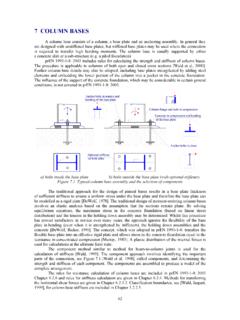
5 Detailed design procedures in the form of a check list are presented for flexible end plates and fin plates. The relevant formulae may be found in the Eurocode. Beam-to-column CONNECTIONS Double angle web cleats Typical bolted double angle cleat CONNECTIONS about both the major and minor axis of a column are shown in Figure These types of connection are popular because they have the facility 36to provide for minor site adjustments when using untorqued bolts in 2 mm clearance holes. Normally the cleats are used in pairs. Any SIMPLE equilibrium analysis is suitable for the design of this type of connection . The one recommended in this publication assumes that the line of action of shear transfer between the beam and the column is at the face of the column. Using this model the bolt group connecting the cleats to the beam web must be designed for the shear force and the moment produced by the product of the end shear and the eccentricity of the bolt group from the face of the column.
6 The bolts connecting the cleats to the face of the column should be designed for the applied shear only. In practice the cleats to the column are rarely critical and the design is almost always governed by the bolts bearing on to the web of the beam. The rotational capacity of this connection is governed largely by the deformation capacity of the angles and the slip between the connected parts. Most of the rotation of the CONNECTIONS comes from the deformation of the angles while fastener deformation is very small. To minimise rotational resistance (and increase rotational capacity) the thickness of the angle should be kept to a minimum and the bolt cross-centres should be as large as is practically possible. When connecting to the minor axis of a column it may be necessary to trim the flanges of the beam but this does not change the shear capacity of the beam.
7 During erection the beam with the cleats attached is lowered down the column between the column flanges. supporting columnsupportedbeamsupporting columnsupportedbeam Figure Typical major and minor axis double angle cleat CONNECTIONS Single angle web cleats Single angle web cleats are normally only used for small CONNECTIONS or where access precludes the use of double angle or end-plate CONNECTIONS . This type of connection is not desirable from an erector s point of view because of the tendency of the beam to twist during erection. Care should be taken when using this type of connection in areas where axial tension is high. The bolts connecting the cleat to the column must also be checked for the moment produced by the product of the end shear force and the distance between the bolts and the centre line of the beam.
8 Flexible end-plates Typical flexible end-plate CONNECTIONS about the major and minor axis of a column are shown in Figure These CONNECTIONS consist of a single plate fillet welded to the end of the beam and site bolted to either a supporting column or beam. This connection is relatively inexpensive but has the disadvantage that there is no room for site adjustment. Overall beam lengths need to be fabricated within tight limits although packs can be used to compensate for fabrication and erection tolerances. The end-plate is often detailed to extend to the full depth of the beam but there is no need to weld the end-plate to the flanges of the beam. Sometimes the end-plate is welded to the beam flanges to improve the stability of the frame during erection and avoid the need for temporary bracing.
9 This type of connection derives its flexibility from the use of relatively thin end-plates combined with large bolt cross-centres. An 8 mm thick end-plate combined with 90 mm cross-centres is usually used for beams up to approximately 450 mm deep. For beams 533 mm deep and over a 10 mm thick end-plate combined with 140 mm 37cross-centres is recommended. The local shear capacity of the web of the beam must be checked and, because of their lack of ductility, the welds between the end-plate and beam web must not be the weakest link. supporting columnsupportedbeamsupporting columnsupportedbeam Figure Typical major and minor axis flexible end-plate CONNECTIONS Detailed Design Procedure 1. Shear capacity of bolt group The shear capacity of the bolt group must be greater than the reaction at the end of the beam.
10 The shear capacity of either the threaded or unthreaded portion of the bolt should be checked. 2. Shear and bearing capacity of the end plate The shear capacity of the end plate must be greater than half the reaction at the end of the beam. The bearing capacity of the end plate must be greater than half the reaction at the end of the beam. 3. Shear capacity of the beam web The shear capacity of the beam web connected to the end plate must be greater than the reaction at the end of the beam. 4. Capacity of fillet welds connecting end plate to beam web The capacity of the fillet weld must be greater than the reaction at the end of the beam. 5. Local shear and bearing capacity of column web The local shear capacity of the column web must be greater than half the sum of the beam end reactions either side of the column web.