Transcription of WELDS- STATIC AND FATIGUE STRENGTH – II
1 WELDS- STATIC AND FATIGUE STRENGTH -II 31 WELDS- STATIC AND FATIGUE STRENGTH II INTRODUCTION In the previous chapter , a detailed account of various welding processes, types of welds, advantages of welded connections etc. were presented. It was seen that welded connections are continuous and more rigid when compared to bolted connections. It was also pointed out that fillet welds and butt welds constitute respectively 80% and 15% of all welds in the construction industry; the balance 5% is made up by plug, slot and spot resistance welds. In this chapter , the behaviour and design of welded connections under various STATIC loading conditions is considered. A typical connection design process is initiated with the design, which is followed by the welding operation and, concludes with inspection. CONNECTION DESIGN In the design of connections, due attention must be paid to the flow of the force through the connection. The transfer of forces should occur smoothly, without causing any stress concentration or cracks.
2 The connections can be either concentric or eccentric. In concentric connections, the forces acting on the connections will essentially be axial in nature, whereas in eccentric connections, the axial forces will be coupled with bending or torsion. These types of connections are described in the following. Concentric connections STATIC STRENGTH of a welded joint depends upon the following factors Type and size of the weld Manner of welding, and Type of electrode used. A primary responsibility of a designer is to select the type and size of the weld . A number of varieties of welds are available. When it is properly chosen with the correct electrode, it develops full STRENGTH of the parent material. The chosen type of weld should develop minimal residual stresses and distortions. As stated in the introduction, butt and fillet welds are the usual forms of welds in practical building construction. Butt welds are used at an edge-to-edge junction or a tee junction.
3 A butt weld connection is made by bringing the plates to be joined face to face edgewise and then filling the cavity formed by edge preparation or by just penetrating the unprepared junction. Butt welds can be either full penetration or partial penetration. Copyright reserved Version II 31-1 WELDS- STATIC AND FATIGUE STRENGTH -II Partial penetration butt welds may be used for STATIC loading, if reduced STRENGTH is acceptable. On the other hand, a fillet weld is made away from the edges of the abutting plates. The joint is formed by welding the members in an overlapped position or by using a secondary joining material. The main advantage of a fillet weld is that the requirements of alignment and tolerance are less rigorous when compared to butt welds. Fillet welding could be applied for lap joints, tee joints and corner joints. A detailed description of these two types of welds and their design requirements are presented in the following. Butt welds Full penetration butt welds are formed when the parts are connected together within the thickness of the parent metal.
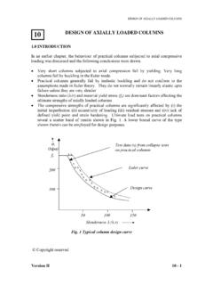
4 For thin parts, it is possible to achieve full penetration of the weld . For thicker parts, edge preparation may have to be done to achieve the welding, which has been discussed in the previous chapter . There are nine different types of butt joints: square, single V, double V, single U, double U, single J, double J, single bevel and double bevel. They are shown in Fig. 1. In order to qualify for a full penetration weld , there are certain conditions to be satisfied while making the welds. The more important ones are given below: (b) Single V (c) Double V (f) Single U(g) Double U (h) Single J (d)Single Bevel (a) Square (e)Double Bevel (j) Double V finished flush on both sides(i)Double J Fig. 1 Different types of butt joints STATIC behaviour of butt welds For butt welds the most critical form of loading is tension applied in the transverse direction (Fig. 2). It has been observed from tests conducted on tensile coupons containing a full penetration butt weld normal to the applied load that the welded joint had higher STRENGTH than the parent metal itself.
5 During the application of the load, the welded portion and the HAZ (Heat Affected Zone of the parent metal) have less transverse contraction compared to the parent metal. The yield stress of the weld metal and the parent metal in the HAZ region was found to be much higher than the parent metal. The increase in yield stress in the HAZ is due to the quenching effect associated with rapid cooling after deposition of the weld . Version II 31-2 WELDS- STATIC AND FATIGUE STRENGTH -II The yield stress of the weld metal is also raised due to the quenching effect. The metal alloys constituting the electrode contribute to the increase in yield stress. These alloys penetrate the parent metal influencing its mechanical properties. Due to the lower yield stress and higher transverse contraction in the parent metal, it experiences a higher true stress. As a consequence, the failure of the coupon always occurs away from the weld .
6 The higher STRENGTH achieved by the welded joint adversely affects its toughness and ductility properties. These negative effects can be minimised by choosing proper electrodes. Longitudinal direction Transverse direction (a) (a) Load applied in transverse direction (b) longitudinal shrinkage restraint (b) Partial penetration welds, shown in Fig. 3, differ in two ways from the full penetration welds: the reduction in cross section and the uncertainty of the weld root quality. Firstly, there is a reduction in the cross section at the joint resulting in overloading and severe plastic straining. Further, the weld root quality cannot be inspected and they cannot be repaired as may be done for full penetration welds. Partial penetration weld Design The butt weld is normally designed for direct tension or compression. However, a provision is made to protect it from shear.
7 Design STRENGTH value is often taken the same as the parent metal STRENGTH . For design purposes, the effective area of the butt-welded connection is taken as the effective length of the weld times the throat size. Effective length of the butt weld is taken as the length of the continuous full size weld . The throat size is specified by the effective throat thickness. For a full penetration butt weld , the throat dimension is usually assumed as the thickness of the thinner part of the connection. Even though a butt weld may be reinforced on both sides to ensure full cross-sectional areas, its effect is neglected while estimating the throat dimensions. Such reinforcements often have a negative effect, producing stress concentration, especially under cyclic loads. Version II 31-3 WELDS- STATIC AND FATIGUE STRENGTH -II Generally speaking, partial penetration welds must be avoided. Partial penetration groove welds are used in non-critical details, so as to avoid back-gouging.
8 If they are considered essential, they should be designed with care. Some codes of practice do not recommend their use in tension. Others specify that they be designed in the same way as fillet welds. This is because the load transfer is not smooth and efficient with partial penetration welds. The effective throat thickness of a partial penetration weld is taken as the minimum thickness of the weld metal common to the parts joined, excluding reinforcement. For stress calculation, a maximum value of reduced effective throat thickness equal to 5/8 of the thickness of the thinner part joined must be used. The unwelded portion in partial penetration butt welds, welded from both sides, shall not be greater than thickness of the thinner part joined, and should be in the central portion. If the stresses are uniform across the throat thickness, the average stress concept may be applied to determine its STRENGTH .
9 Connections with partial penetration welds with welding on only one side is generally avoided under tensile load due to the eccentric loading involved. Otherwise, the eccentricity effects should be considered in the design. Unsealed butt welds of V, U, J and bevel types and incomplete penetration butt welds should not be used for highly stressed joints and joints subjected to dynamic and alternating loads. Intermittent butt welds are used to resist shear only and the effective length should not be less than four times the longitudinal space between the effective length of welds nor more than 16 times the thinner part. They are not to be used in locations subjected to dynamic or alternating stresses. Some modern codes do not allow intermittent welds in bridge structures. For butt welding parts with unequal cross sections, say unequal width, or thickness, the dimensions of the wider or thicker part should be reduced at the butt joint to those of the smaller part.
10 This is applicable in cases where the difference in thickness exceeds 25 % of the thickness of the thinner part or mm, whichever is greater. The slope provided at the joint for the thicker part should not be steeper than one in five [ (a) &(b)]. In instances, where this is not practicable, the weld metal is built up at the junction equal to a thickness which is at least 25 % greater than the thinner part or equal to the dimension of the thicker part [Fig. 4(c)]. Where reduction of the wider part is not possible, the ends of the weld shall be returned to ensure full throat thickness. 4(a) Taper not exceeding 1 in 5 4(c) t Not less than t/4 OR up to the dimension of thicker material 4(b) Taper not exceeding 1 in 5 weld Fig. 4 Butt welding of members with (a)&(b) unequal thickness (c) unequal width Version II 31-4 WELDS- STATIC AND FATIGUE STRENGTH -II Permissible stresses for butt welds are assumed same as for the parent metal with a thickness equal to the throat thickness.