Transcription of 07-GB Column Bases - cvut.cz
1 7 Column Bases . A Column base consists of a Column , a base plate and an anchoring assembly. In general they are designed with unstiffened base plates, but stiffened base plates may be used where the connection is required to transfer high bending moments. The Column base is usually supported by either a concrete slab or a sub-structure ( a piled foundation). prEN 1993-1-8: 2003 includes rules for calculating the strength and stiffness of Column Bases . The procedure is applicable to columns of both open and closed cross sections [Wald et al, 2000].
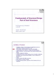
2 Further Column base details may also be adopted, including base plates strengthened by adding steel elements and embedding the lower portion of the Column into a pocket in the concrete foundation. The influence of the support of the concrete foundation, which may be considerable in certain ground conditions, is not covered in prEN 1993-1-8: 2003. Anchor bolts in tension and bending of the base plate Column flange and web in compression Concrete in compression and bending of the base plate Anchor bolts in shear Optional stiffener on both sides a) bolts inside the base plate b) bolts outside the base plate (with optional stiffener).
3 Figure Typical Column base assembly and the selection of components The traditional approach for the design of pinned Bases results in a base plate thickness of sufficient stiffness to ensure a uniform stress under the base plate and therefore the base plate can be modelled as a rigid plate [DeWolf, 1978]. The traditional design of moment-resisting Column Bases involves an elastic analysis based on the assumption that the sections remain plane. By solving equilibrium equations, the maximum stress in the concrete foundation (based on linear stress distribution) and the tension in the holding down assembly may be determined.
4 Whilst this procedure has proved satisfactory in service over many years, the approach ignores the flexibility of the base plate in bending (even when it is strengthened by stiffeners), the holding down assemblies and the concrete [DeWolf, Ricker, 1990]. The concept, which was adopted in prEN 1993-1-8: transfers the flexible base plate into an effective rigid plate and allows stress in the concrete foundation equal to the resistance in concentrated compression [Murray, 1983]. A plastic distribution of the internal forces is used for calculations at the ultimate limit state.
5 The component method similar to method for beam-to- Column joints is used for the calculation of stiffness [Wald, 1995]. The component approach involves identifying the important parts of the connection, see Figure [Wald et al, 1998], called components, and determining the strength and stiffness of each component. The components are assembled to produce a model of the complete arrangement. The rules for resistance calculation of Column Bases are included in prEN 1993-1-8: 2003. Chapter and rules for stiffness calculation are given in Chapter Methods for transferring the horizontal shear forces are given in Chapter Classification boundaries, see [Wald, Jaspart, 1999], for Column base stiffness are included in Chapter 62.
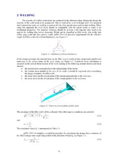
6 Q&A Elastic Resistance of a base Plate Why is the resistance of a base plate based on its elastic properties? _____. By limiting the deformations of the base plate to the elastic range a uniform stress under the base plate may be assumed, see Figure It also ensures that the yield strength of the base plate is not exceeded. The effective bearing area of a flexible base plate is based on an effective width c. Figure Finite element model of base plate T stub and concrete block in compression, undeformed and deformed mesh and the principal stress in concrete [Wald, Baniotopoulos, 1998].
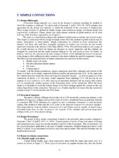
7 M. c c c c c t c c Figure Engineering model of the base plate The elastic bending moment resistance per unit length of the base plate should be taken as 1. M = t 2 f yd , ( ). 6. and the bending moment per unit length [DeWolf, Sarisley, 1980], acting on the base plate represented by a cantilever of span c, see Figure , is 1. M = f j c2 , ( ). 2. where fj is concrete bearing strength. When these moments are equal, the bending moment resistance of the base plate is reached and the formula for evaluating c can be obtained from 1 1.
8 F j c2 = t 2 f y ( ). 2 6. as fy c=t . ( ). 3 f j M0. 63. Q&A base Plate Resistance with Low Quality Grout In prEN 1993-1-8, the joint coefficient j is taken as 2/3 when the grout has at least 20% of the characteristic strength of the concrete foundation. What value should be taken when the strength of the grout is smaller? _____. The influence of low quality grout has been studied experimentally and numerically. It was found that the thin layer of grout does not affect the resistance of the concrete in bearing.
9 It is expected that the grout layer is in three-dimensional compression, the grout between the concrete and the base plate, is similar to a liquid. Most of the mortars have a higher resistance compared to the material of the concrete block [Stark, Bijlaard, 1988]. In such cases, the grout layer may be neglected. In other cases, the bearing resistance can be checked, assuming a distribution of normal stress under the effective plate at an angle of 45 , see Figure Where the thickness of the grout is more than 50 mm, the characteristic strength of the grout should be at least the same as that of the concrete foundation [prEN 1993-1-8: 2003].
10 Further information is given in Q&A c c t tg tg tg tg 45 . 45 . Figure The stress distribution in the grout Q&A Comparison of Concrete Strength Calculation according to EC2 and EC3. It seems the results from calculating the bearing strength of a Column base fj are the same as those given in prEN 1992-1-1. According to prEN 1992-1-1 the strength is Ac 1. FRdu = Ac 0 f cd 3,3 Ac 0 f cd . Ac 0. According to prEN 1993-1-8 the maximum value for kj is 5,0. For this value we get a value of 2. f j = 5 f cd = 3 ,33 f cd 3.