Transcription of 1 – Introduction to AutoCAD - University of New Mexico
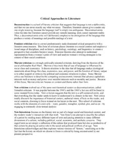
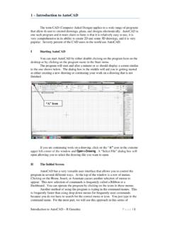
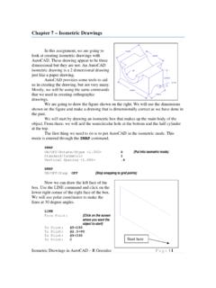
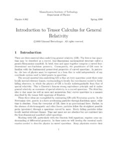
1 1 Introduction to AutoCAD . The term CAD (Computer Aided Design) applies to a wide range of programs that allow th user to created drawings, plans, and designs electronically. AutoCAD is one such program and it main claim to fame is that it is relatively easy to use, it is very comprehensive in its ability to create 2D and some 3D drawings, and it is very popular. Seventy percent of the CAD users in the world use AutoCAD . I Starting AutoCAD . You can start AutoCAD by either double clicking on the program Icon on the desktop or by clicking on the program name in the Start menu. The program will start and after a minute or so should display a screen similar to the one shown below. The dialog box in the middle will aid you in getting started at either creating a new drawing or continuing your work on a drawing that is not finished.
2 A Icon If you are continuing work on a drawing, click on the A icon in the extreme upper left corner of the window and Open->Drawing. A Select File dialog box will open allowing you to select the drawing file you want to open. II The Initial Screen AutoCAD has a very versatile user interface that allows you to control the program in several different ways. At the top of the window is a row of menus. Clicking on the Home, Insert, or Annotate causes another selection of menus to appear. This new selection of commands is frequently called a Ribbon or a Dashboard. You can operate the program by clicking on the icons in these menus. Another method of using the program is typing in the command names. This is frequently faster than using drop down menus for frequently used commands because you do not have to search for the correct menu or icon.
3 You just type in the command name. For the most part, we will use this approach in this series of Introduction to AutoCAD R Greenlee Page |1. tutorials. The commands that you type will appear at the bottom of the of the AutoCAD window. III The LINE Command Now that you have started AutoCAD and configured tool bars you want, you are ready to start learning to use the program. We will start with relatively simple commands and eventually, in later lessons, look at some of the more complex things that AutoCAD can do. The first command we will look at drawing straight lines. At the keyboard, type: line and press the ENTER key. You can use either upper or lower case when you type in AutoCAD commands. The program will respond with: Specify First Point: Each line has a beginning and ending point and the program wants you to specify the beginning point of the line.
4 You enter the beginning point by either typing the point coordinates at the keyboard or by clicking the mouse on a location of the screen where you want the line to begin. It is certainly much simpler to click with the mouse than it is to type in coordinates but engineering drawings are drawn precisely to scale and for the most part we will have to enter coordinates from the keyboard. When you type a coordinate, enter the X or horizontal coordinate first followed by a comma and the Y or vertical coordinate. You cannot enter a space between the two coordinates. AutoCAD interprets a space as the ENTER key and assumes that you have finished entering the coordinates. For Example, you could type: Specify First Point: ,6. The coordinate is the X or horizontal coordinate and the 6 is the vertical coordinate.
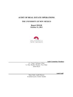
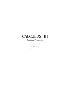
5 After you enter the coordinates, press the enter key. The enter key tells the program that you have entered the first coordinate and are ready to enter the coordinates for the next which will be the end of the line. The program responds by displaying: To Point: If you want a horizontal line that is 5 units long, you enter the coordinates @5,0 which is shown below. To Point: @5,0 The @ sign tells the program this coordinate is measured from the ,6 Line Drawn ,6. last coordinate entered. In other Introduction to AutoCAD R Greenlee Page |2. words, it says place the end if the line 5 units horizontally from the beginning point and 0 units vertically. The line drawn is shown above. Using the @ sign to specify relative coordinates is easier than specifying absolute coordinates without the @ sign.
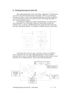
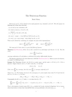
6 The first point we drew had an absolute coordinate of ,6 and the second point had an absolute coordinate of ,6 since it is displaced 5 units horizontally from the first point. We will continue with this to create the object shown on the right. It has lines, an arc, and a circle. We have drawn the first and we will continue drawing the rest of the lines. As a shortcut, you can start the LINE command by typing L instead of the entire word LINE. Many AutoCAD commands can be abbreviated to just the first letter of the command. IV Continue Drawing the Object We can continue drawing the object shown on the right by adding more lines. If the line command is still operating, press ENTER to end it. First Line We will start it again to draw the remaining lines.
7 ,6 ,6. You can draw the remaining lines by typing: line Specify First Point: ,6 {these are the coordinates of the end of the first line we drew}. To Point: To Point To Point To point {Press ENTER without entering coordinates. This will end the line command}. When you have finished ,10. entering all of the coordinates, you should have the object shown on the right. V Erasing Objects First Line AutoCAD calls lines, circles, arcs and other things that you draw objects. You can erase any of these ,6 ,6. objects by typing the command: ERASE. The program will respond with: Introduction to AutoCAD R Greenlee Page |3. Select Objects: You select the objects (lines, arcs, circles, etc.) in several different ways. The easiest way is to click on the object you want to erase.
8 When you do, the object is redrawn as a dashed line. This shows the object has been selected for deletion. Click on all of the objects that you want to erase then press the ENTER key to terminate the command and erase the objects. AutoCAD commands frequently have command modifiers that change the way the command works. For the ERASE command, you can type: ERASE ALL. and AutoCAD selects all of the objects in the drawing for erasure. The word ALL. modifies the way command works. Another option is: ERASE W. The W stands for window which allows you to select the objects by drawing a box around them. First click above and to the right of the objects that you want to erase. When you do, the mouse pointer changes to an elastic box with one corner fixed at the place where you clicked.
9 Move the mouse until the box completely covers the information you want selected and click the mouse button again. All of the objects inside the box will be selected for erasure. Press the ENTER key to erase the objects. You can type E to start the ERASE command. VI Oops If you make a mistake and erase something that you did not want to erase, type: OOPS. to undo the last erasure. OOPS always undoes the last erasure even though you have continued with other commands since the objects were erased. VII Canceling a Command If you start a command and do not want to complete it, you can press the Esc key to cancel the command. For some commands, you may have to press the key more than once. Keep pressing the Esc key until you see the Command: prompt at the bottom of the screen.
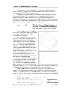
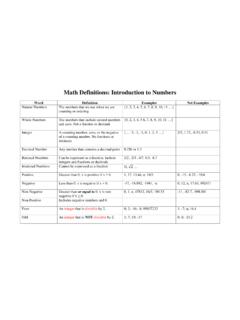
10 VIII Drawing Arcs The ARC command is used to draw arcs. We can use this command to draw the semicircle on the left side of the object. Enter: Introduction to AutoCAD R Greenlee Page |4. Arc Specify start point of arc or [Center]: ,10 {The end point of the last line we drew}. Specify second point of arc or [Center/End]: c {Enter C to tell the program we want to enter the center point instead of the end point of the arc}. Specify center point of arc: @0,-2 {The center of the arc is 2. units below the start point}. Specify end point of arc: @0,-2 {The end of the arc is 2 units below the center}. The completed arc is shown in ,10. the drawing on the right. Unless otherwise specified, AutoCAD will draw arcs in a counterclockwise (anticlockwise) direction.