Transcription of 10-MINUTE TUTORIAL DIGITAL LOGIC CIRCUIT MODELING …
1 10-MINUTE TUTORIAL DIGITAL LOGIC CIRCUIT MODELING AND SIMULATION WITH MULTISIM Multisim is a schematic capture and simulation program for analog, DIGITAL and mixed analog/ DIGITAL circuits, and is one application program of the National Instruments CIRCUIT Design Suite , which also includes printed CIRCUIT board design tools and an interface to the ELVIS breadboarding platform. It is suggested that you begin by taking a few minutes to read the short Multisim TUTORIAL , which is presented as Chapter 2 of Getting Started with NI CIRCUIT Design Suite , which can be accessed via: Start Menu > All Programs > National Instruments > CIRCUIT Design Suite > Documentation > Getting Started The basic steps in MODELING and analysis of a DIGITAL LOGIC CIRCUIT are: 1. Open Multisim and create a design.
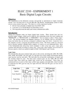
2 2. Draw a schematic diagram of the CIRCUIT (components and interconnections). 3. Define DIGITAL test patterns to be applied to the CIRCUIT inputs to stimulate the CIRCUIT and connect signal sources to the inputs to produce these patterns. 4. Connect the CIRCUIT outputs to one or more indicators to display the response of the CIRCUIT to the test patterns. 5. Run the simulation and examine the results, copying and pasting Multisim windows into lab reports and other documents as needed. 6. Save the design. Step 1. Open Multisim and create a design Multisim is opened from the Start Menu: Start Menu > All Programs > National Instruments > CIRCUIT Design Suite > Multisim (Version numbers may differ) This creates a blank design called Design1 , as illustrated in Figure 1.
3 Save the file with the desired design name via menu bar File>Save As to use the standard Windows Save dialog, shown in Figure 2. Navigate to the directory in which you want to save your design, enter the desired file name, and click the Save button. The default file extension for Multisim design files is .ms11. Note: Create a separate directory on a flash drive or your network drive (H:) to be used exclusively for storing your Multisim designs and related files. This will ensure that (1) your files will be accessible from any lab computer and (2) your Multisim files will not be mixed in with your other files. It is also a good idea to periodically make backup copies of your files as protection against loss of data. A previously created design can be opened via File>Open.
4 In the dialog window, navigate to the directory in which the design is stored, select the file, and click the Open button. Figure 1. Blank design with default name Design 1 Figure 2. File > Save As dialog window. Design to be saved as file CIRCUIT Window Design Name Component Toolbar Menu Bar Instruments Step 2. Draw a schematic diagram of the CIRCUIT Placing Components A schematic diagram comprises one or more CIRCUIT components, interconnected by wires. Optionally, signal sources may be connected to the CIRCUIT inputs, and indicators to the CIRCUIT outputs. Each component is selected from the Multisim library and placed on the drawing sheet in the CIRCUIT Window (also called the Workspace). The Multisim library is organized into groups of related components (Transistors, Diodes, Misc DIGITAL , TTL, etc.)
5 Each group comprises one or more families , in which the components are implemented with a common technology. For designing and simulating DIGITAL LOGIC circuits in ELEC 2210, two groups are to be used: Misc DIGITAL (TIL family only) and TTL . The Misc DIGITAL group has three families of components, of which family TIL contains models of generic LOGIC gates, flip-flops, and modular functions. These components are technology-independent, which means that they have only nominal CIRCUIT delays and power dissipation, unrelated to any particular technology. Generic components can be used to test the basic functionality of a design, whereas realistic timing information requires the use of technology-specific part models, such as those in the TTL group. To place a component on the drawing sheet, select it via the Component Browser, which is opened via the component toolbar or the menu bar.
6 From the menu bar, select Place>Component to open the Component Browser window, illustrated in Figure 3. You can also open this window by clicking on the Misc DIGITAL icon in the component toolbar. On the left side of the window, select Master Database , group Misc DIGITAL , and family TIL . The component panel in the center lists all components in the selected family. Scroll down to and click on the desired gate (NAND2 in Figure 3); its symbol and description are displayed on the right side of the window. Then click the OK button. The selected gate will be shown on the drawing sheet next to the cursor; move the cursor to position the gate at the desired location, and then click to fix the position of the component. The component can later be moved to a different location, deleted, rotated, etc.
7 By right clicking on the component and select the desired action. You may also select these operations via the menu bar Edit menu. After a component has been positioned, the component browser is redisplayed and additional components can be placed by repeating the above actions. When the last component has been placed, click the Close button to close the component selection window. You may return to the component browser at any time to add additional components. Figure 3. Component Browser: Misc DIGITAL TIL family NAND2 gate component selected. Figure 4. A third NAND2 gate is about to be placed on the drawing sheet. The TIL family part naming convention is as follows. Look at the symbol and function panels on the right side of the component selection window to determine the specific function of a selected component.
8 1. Basic LOGIC gates: ANDx, NANDx, NOT, NORx, ORx, XNORx, XORx, where x is the number of gate inputs (2-8). 2. Flip flops: D_FF, JK_FF, SR_FF, T_FF, and latches D_LATCH, SR_LATCH, plus versions that have active-high or active-low asynchronous Set and Reset pins (ex. D_FF_POSSR and D_FF_NEGSR, respectively). 3. Standard DIGITAL modules: multiplexers, decoders, encoders, counters, ALU, BCD-to-7 segment decoder, registers, shift registers, etc. 4. DIGITAL_PULLUP, DIGITAL_PULLDOWN to pull a pin to a constant LOGIC 1 and 0, respectively. Figure 5 shows the schematic diagram with four placed components. Note that each placed gate has a designator (U2, U3, U4, U5), which can be used when referring to that gate. You can change a designator by right clicking on the component, selecting Properties, and entering the desired name on the Label tab.
9 Figure 5. Schematic diagram with all placed components. Drawing Wires Wires are drawn between component pins to interconnect them. Moving the cursor over a component pin changes the pointer to a crosshair, at which time you may click to initiate a wire from that pin. This causes a wire to appear, connected to the pin and the cursor. Move the cursor to the corresponding pin of the second component (the wire follows the cursor) and click to terminate the wire on that pin. If you do not like the path selected for the wire, you may click at a point on the drawing sheet to fix the wire to that point and then you can move the cursor to continue the wire from that point. You may also initiate or terminate a wire by clicking in the middle of a wire segment, creating a junction at that point.
10 This is necessary when a wire is to be fanned out to more than one component input. A partially-wired CIRCUIT , including one junction point, is illustrated in Figure 6. Figure 6. Partially wired CIRCUIT , with one junction point. Step 3. Generating test input patterns. To drive CIRCUIT simulations, Multisim provides several types of sources to generate and apply patterns of LOGIC values to DIGITAL CIRCUIT inputs. Sources are placed on the schematic sheet and connected to CIRCUIT inputs in the same way as CIRCUIT components, selecting them from the Digital_Sources family of the Sources group in the component browser. Note that there is a Place Source shortcut icon in the tool bar. There are three basic DIGITAL sources: 1. DIGITAL_CONSTANT this is a box with a constant LOGIC 1 or 0 output, and would be used where the LOGIC values is not to be changed during simulation.