Transcription of ELEC 2210 - EXPERIMENT 1 Basic Digital Logic Circuits
1 REV 8/18/09 Roppel 1 ELEC 2210 - EXPERIMENT 1 Basic Digital Logic Circuits The experiments in this laboratory exercise will provide an introduction to Digital electronic Circuits . You will learn how to use the IDL-800 Bit Bucket breadboarding system to build Circuits using common Logic gates. The objectives of this EXPERIMENT include: Objectives Review Basic principles of Digital Logic from ELEC 2200 Learn how to use the Bit Bucket breadboarding system Develop professional lab skills and written communication skills.
2 Almost all computers today use binary Digital Logic Circuits . These Circuits have just two possible output voltages, which can be called by any contrasting terms; the most common are HIGH/LOW , or TRUE/FALSE , or ONE/ZERO. Such an output is called a binary digit, or bit. The decimal numbers and alphabet characters we are familiar with are converted to binary bits before they are fed into a computer s arithmetic Logic unit (ALU). Inside the ALU, the computer executes a program and generates binary results.
3 The binary results are converted back to decimal numbers, alphabet letters, graphics, or sound so we can understand them. Most of the fundamental data processing inside computers is done using Logic gates. Logic gates combine individual bits according to certain rules. These rules, taken together, form the basis of Boolean algebra, which you studied in depth in ELEC 2200 Digital Logic Circuits . Introduction Logic Gates We will introduce the most common Logic gates in this section, including the AND, OR, XOR, NOT, NOR, and NAND.
4 For each gate, we will show the circuit symbol, the Boolean algebra Logic function, and the truth table. The truth table lists all possible combinations of inputs, and the resulting output for each. The three most common gates are the AND, OR and NOT (inverter) gates from which any Digital Logic circuit can be constructed. These gates are summarized below in terms of their Logic symbol, Logic equation, and truth table, where it should be noted that the NOT gate has only one input while the AND and OR gates can have two or more inputs.
5 Logic Gate AND OR NOT (inverter) Symbol Logic Equation Out = In1 In2 Out = In1+In2 Out =In Truth Table In1 In2 Out 0 0 0 0 1 0 1 0 0 1 1 1 In1 In2 Out 0 0 0 0 1 1 1 0 1 1 1 1 In Out 0 1 1 0 In Out In1 In2 Out In1 In2 Out REV 8/18/09 Roppel 2 Other common gates include the NAND, NOR, exclusive-OR (XOR), and exclusive-NOR (XNOR) gates. While the NAND and NOR gates are functionally complete (meaning that any Digital Logic circuit can be constructed from either one of these gates), the XOR and XNOR gates are not functionally complete and, therefore, are not considered to an elementary Logic gate by most designers.
6 These gates are summarized below in terms of their Logic symbol, Logic equation, and truth table where it should be noted that the NAND and NOR gates (like their AND and OR counterparts) can have two or more inputs, while the XOR and XNOR gates generally have only two inputs. The NAND and NOR gates are a combination of an AND gate and NOT gate and a combination of an OR gate and NOT gate, respectively, as can be observed by comparing their truth tables. Similarly, the exclusive -NOR (XNOR) gate has the inverse output of the XOR gate truth table.
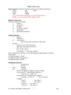
7 Logic Gate NAND NOR XOR XNOR Symbol Logic Equation Out = In1 In2 Out = In1+In2 Out = In1 In2 Out = (In1 In2) Truth Table In1 In2 Out 0 0 1 0 1 1 1 0 1 1 1 0 In1 In2 Out 0 0 1 0 1 0 1 0 0 1 1 0 In1 In2 Out 0 0 0 0 1 1 1 0 1 1 1 0 In1 In2 Out 0 0 1 0 1 0 1 0 0 1 1 1 DeMorgan s Theorems also relate the operation of the NAND and NOR gates to AND and OR gates as follows: ( AB) = A+B ()A B AB+= DeMorgan s Theorems in conjunction with the Involution Theorem, which states that ()A= A, can be used to convert any 2-level AND-OR implementation of a sum-of-products (SOP) expression to an all-NAND gate implementation of the circuit.
8 Similarly, any 2-level implementation of a product-of-sums (POS) expression can be converted to an all-NOR gate implementation of the circuit. Logic Families A Logic family is a complete set of Logic gates that are manufactured using a particular type of electronic circuitry. There are numerous commercially available Logic families to suit different design requirements. The most common Logic families are listed in the table below, together with their relative advantages and disadvantages.
9 Acronym Full name Advantages Disadvantages CMOS Complementary metal-oxide semiconductor Lowest power consumption. Most common Logic family- used in all microcomputer chips today. Easily damaged by static discharge and voltage spikes. In1 In2 Out In1 In2 Out In1 In2 Out In1 In2 Out REV 8/18/09 Roppel 3 TTL Transistor-transistor Logic Earliest developed. Most rugged least susceptible to electrical damage. Consumes more power than CMOS not suitable for battery operated devices. ECL Emitter-coupled Logic Fastest available Logic family Consumes more power than CMOS.
10 Requires extreme care in wiring. The standard part number for the TTL NAND gate is 7400. However, most manufacturers have their own designation which includes these numbers, but adds some extra characters. The following are examples of valid part numbers you might find on a "7400" chip: SN7400N, MM74C00N, SN74LS00N, SN74H00N, etc. In addition to these, there will often be another part code stamped on the chip by the manufacturer, and there might be a code stamped underneath the chip as well.