Transcription of A Gray-Code Current Mode ADC Structure
1 A Gray-Code Current Mode ADC StructureBogdan M. Wilamowski Dept. of Electrical and Computer Engineering Auburn University Alabama, 36849-5201, Mahmut Ersin Sinangil and G nhan D ndar Dept. of Electrical and Electronic Engineering Bogazici University Istanbul, TURKEY Abstract Analog to Digital Converters (ADC) are one of the most critical blocks in the area of electronics. This paper presents two new circuits for Gray-Code Current -mode analog to digital conversion which employs absolute value operation. The implementations of two different 5-bit converter circuits are discussed in this paper. m CMOS technology with 5V power supply voltage is used for the circuits. Most processing is done in the digital domain whereas the signals in the world we live in are analog. Analog to Digital conversion which provides the link between these two domains is an extremely important research area.
2 Moreover, Gray coding is a well known phenomenon with several advantages such as low power consumption, fewer glitches, and shorter transitions. Bringing these two concepts together, namely, building a Gray Coded ADC, is not a new idea. Such a circuit was discussed in [1] and a modified version is also given in [2, 3]. More recent research [4, 5] also discusses some important applications where Gray-Code Current -mode ADC can be used ( image processing applications [5]). Gray-coding ADC s give better results regarding offset errors in circuit realizations as compared to their binary counterparts [6]. The Gray-Code A/D conversion presented in this paper is based on the absolute value operation. The circuits presented are all Current -mode and take IIN as their input.
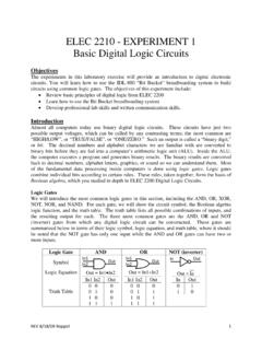
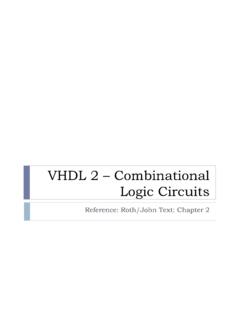
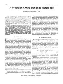
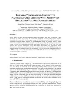
3 A fixed Current , IREF, is subtracted from the input Current in each stage and the remaining Current is rectified and doubled in magnitude. By repeating this process as shown in Fig. 1, a Gray coding scheme can be realized. The first bit on the left is the Most Significant Bit and the last bit on the right is the Least Significant Bit. A demonstration of this concept is done in Matlab as shown in Fig. 2. IREF is taken as 150 Aand the input is swept from 0 to 150 A. By looking at the sign of the Current at various points, the Gray-coded form of the input can be generated. For the implementation of this algorithm, an absolute value circuit with a wide operating range and very good precision is required. There are many proposed absolute value circuits in the open literature.
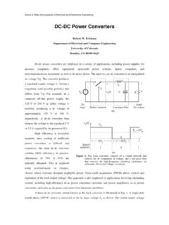
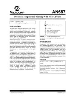
4 The absolute value circuit is the most crucial building block of this design. Its properties determine the operating range and precision of the overall circuit . Hence, a thorough simulation of the absolute value block is necessary to ensure correct operation of the overall circuit . Figure 1. Block Diagram of the Gray code Conversion Algorithm050100150-150-100-50050100150 Iin(mA)Bit(0) - Bit(4) (mA)Bit(4)Bit(3)Bit(2)Bit(1)Bit(0)Figure 2. The result of the gray code conversion algorithm simulated in MatlabIEEE MELECON 2006, May 16-19, Benalm dena (M laga), Spain1-4244-0088-0/06/$ 2006 AND DESIGN OF THE absolute value CIRCUITThe circuit in Fig. 3 is a half wave rectifier and employs seven transistors. The branches on which transistors M2 and M4 are placed are the key elements in this design. When the input Current IIN is positive, M2 is ON and the excess Current on M1 due to the input Current is mirrored to output over M3.
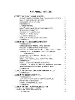
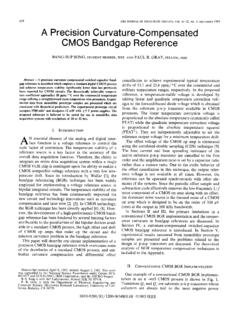
5 When the input Current is negative, M2 is off and hence M1 is in the resistive region. The output Current is nearly zero because the Current supplied by M6 is equal to the Current pulled by M3. As a result, the circuit works as a half-wave rectifier. Figure 3. Half-Wave Rectifier circuit By using another circuit with the same logic, the other half of the signal can also be rectified. Hence, by subtracting the output currents of the two portions, a full-wave rectifier can be realized as shown in Fig. 4. Figure 4. absolute value circuit For the circuit in Fig. 4, a power supply of 5V is used and the bias currents for the circuit are A Current mirror realized with NMOS transistors are used for the subtraction operation. Since the algorithm for Gray code conversion requires a 2*ABS() operation, another Current mirror realized with PMOS transistors are used to multiply the output Current by two.
6 Another absolute value circuit is given in Fig. 5. This circuit employs sixteen transistors and again uses 5V power supply. Transistors M3, M4, M5, M8, M9, M10 and M19 constitute the rectifying operation whereas M11, M12, M13 and M14 are used for converting the Current to a binary voltage. Transistors M15 and M16 are used to subtract the reference Current from the output. Figure 5 absolute value circuit The layout of the circuit in Fig. 4 is given in and the extracted netlist is used for the simulations. The layout of the circuit in Fig. 5 which is simpler is not given in this paper due to space considerations. Transient analysis results for the absolute value circuit in show that this circuit can work in the range [0,200 A] with good linearity, up to a frequency of 1 MHz. The DC analysis and transient analysis results of the same circuit are given in Figures 7 and 8, respectively to illustrate these results.
7 The transient analysis results of the circuit in Fig. 5 show that this circuit can work up to a few hundred kHz with good linearity in the range [0 150 A]. The simulation results for this circuit are given in Figures 9 and 10. 36 Figure 6. Layout of the absolute value circuit in Fig. 4 Figure 7. DC Analysis of the absolute value circuit for the range [-200uA 200uA]Figure 8. Transient Analysis of the absolute value circuit in at 1 MHzFigure 9 DC Analysis of the absolute value circuit in Figure 10 Transient analysis of the absolute value circuit in at 100kHz. In order to depict the effects of parameter variations on the design, Monte Carlo Simulations are done by varying W, L and VTHO parameters of each transistor according to values supplied by the manufacturer. The Monte Carlo simulation results for the circuit of are given in Fig.
8 11 and results for the circuit in Fig 5 are given in Figure 11. Result of Monte Carlo Analysis for the circuit in Fig. 4 37 Figure 12 Result of Monte Carlo Analysis for the circuit in Fig. 5 OF THE GRAY code CONVERTER circuit WITH THE absolute value OPERATIONA fter designing the absolute value circuits, 5-bit Gray-Code Current -mode A/D converters are constructed by cascading these absolute value circuits as shown in NMOS Current mirrors are used to subtract IREF currents at various nodes in the design. The conversion of the currents to digital words is not discussed in this paper but different approaches can be used to do this. Transistors M13, M14, M15 and M16 in are used for this purpose to illustrate the concept. An external circuit can also be used for each absolute value cell to convert the Current signal to a digital bit as discussed in [4], The output waveforms of the ADCs constructed with the absolute value circuits discussed above are given in Figures 13 and 14.
9 The DC analysis is done for an input Current in the range [0,150 A.] for the first circuit and [0, 10 A] for the second circuit . Figure 13. DC Analysis for the 5-bit Converter circuit realized with the absolute value circuit in Figure 14. DC Analysis for the 5-bit Converter circuit realized with the absolute value circuit in V. CONCLUSIONThe design presented in this paper is based on Gray-Coding A/D Conversion. Two different circuits operating for currents in the range [0,150 A] and [0, 10 A] are presented. The range of operation for both of these circuits is around 200 A. The highest frequency possible with the first circuit is around one megahertz whereas for the second circuit , it is a few hundred kilohertz. The first circuit is more complex and consumes more power than the second circuit presented in this paper.
10 The properties of the circuits heavily depend on the characteristics of the absolute value circuit block so the realization of a linear rectifying circuit is very important. The absolute value circuits used in this work are by no means the only solution. By employing other absolute value circuits, different behavior can be observed. The reason for illustrating the behavior with two different absolute value circuits is to prove the operation of the general concept irrespective of the specific work includes evaluation of different types of absolute value circuits to realize more reliable and less area consuming Gray-Code Current -Mode ADC s. Furthermore, these circuits will be implemented as chips. Finally, it is planned to use the Gray-Code Current -Mode ADC s in larger systems.