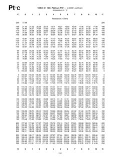
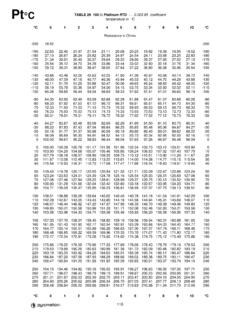
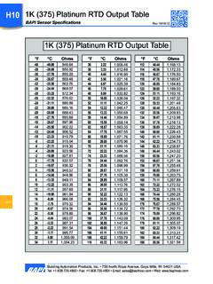
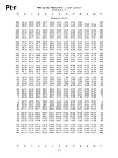
Transcription of 100 OHM PLATINUM RTD RANGEABLE TRANSMITTER
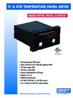
1 SMI-T81U-902TM KELE FAX 901-372-2531 USA 901-937-4900 International 901-382-6084100 OHM PLATINUM RTD RANGEABLE TRANSMITTERMODEL T81 USOLUTIONSTM ( ) ( )in(cm)Height: ( )DESCRIPTIONThe Model T81U PLATINUM RTD RangeableTransmitter is a two-wire, 4-20 mA TRANSMITTER designedfor use with Type 81 100 PLATINUM RTD sensors. Thetransmitter is available in three standard ranges, or itcan be set for any range between -30 to 250 F (-34 to121 C) with a minimum span of 40 F (22 C).To adjust the Model T81U, set the DIP switches tomatch the desired range and use the zero and spanpots to fine tune.
2 A high accuracy digital ohmmeter anddecade box are Model T81 Uhas a special 20 mA loop calibrationtest signal to provide easy system verification. Simplymove the bottle plug jumper from NORM to 20, and thetransmitter will output a constant 20 mA. The Loop UpLED provides power indication for the 4-20 mA Dip switch RANGEABLE Loop calibration test signal Snap-track mounting Loop-powered LED indication 18-month warrantySensor input100 platinumTCR / / COutput4-20 mA, loop-poweredRangeability limits-30 to 250 F (-34 to 121 C)Min span40 F (22 C) F or of spanLoop calibration output20 mA VDC-45 VDCMax impedance675 at 24 VDC Ambient operating temp0 to 140 F (-18 to 60 C)Humidity0% to 95% noncondensingDimensions "W x "L x 1"H( x x cm)
3 AgencyCESPECIFICATIONSDIMENSIONSKELE FAX 901-372-2531 USA 901-937-4900 International 901-382-6084 Power VDC4-20 MASignalLOOPNORMTEMPSENSORTEMPSENSOR20 LOOP100 385 PlatinumRTD Sensor(sold separately)MODEL T81 URANGE1 2 3 4 5 LOOP UP SPANZEROLoop PowerLEDWIRINGORDERING INFORMATIONMODEL DESCRIPTIONT81U4-20 mA RANGEABLE RTD TransmitterRANGE 2-20 to 140 F (-29 to 60 C)30 to 100 F (-18 to 38 C)430 to 240 F (-1 to 116 C)XR Special RangeSENSOR TYPE TRANSMITTER onlyDST-D81-XW Duct sensor*OST-O81 Outside air sensor*WST-W81-XW Immersion sensor* with wellAVST-AV81H Averaging sensor*XWMS ingle gang weather resistant box (mounted without sensor)T81U2 DExample.
4 T81U-2-D TRANSMITTER with range of -20 to 140 F (-29 to 60 C) mounted and wired in duct sensor enclosure Indicate at time of order*Includes sensor mounted and wiredKELE FAX 901-372-2531 USA 901-937-4900 International 901-382-60843 The T81U RTD TRANSMITTER can be field-calibrated by using the ZERO and SPAN potentiometers and DIP the step-by-step instructions below to calibrate the T81U to the desired temperature range. For informationabout accuracy, see Special Notes on Field Calibration on the reverse Assemble required equipment: temperature TRANSMITTER , 24 VDC power supply, decade box [Model RSU- 280 (Newark) or equal], digital VOM [Fluke Model 87 (Newark) or equal], trim screwdriver, RTD Resistance Chart (see Temperature section of Kele catalog).
5 Step2 Using the RTD Resistance vs. Temperature Chart for 1000 PLATINUM 375 Curve, select and record the resistance values for the high and low temperatures in the desired range. Designate these values as LOW TEMP OHMS and HIGH TEMP Calculate the calibration factor using the ohms recorded in Step 2:Step4 Using the resistance decade box, select a resistance value within one ohm of the low temperature ohms in Step 2. Do not use a lower value. Measure this resistance with the VOM and record the actual value accurate to hundredths of an ohm. This value will be referred to as MIN REF a resistance value within one ohm of the high temperature ohms in Step 3.
6 Do not use a higher value. Measure this resistance with the VOM and record the actual value accurate to hundredths of an ohm. This value will be referred to as MAX REF the low mA reference:Calculate the high mA reference:Step5 Connect the TRANSMITTER as shown:CAL FACTOR = HIGH TEMP OHMS - LOW TEMP OHMS16 LOW MA REF = MIN REF OHMS - LOW TEMP OHMSCAL FACTOR+ 4 HIGH MA REF = MAX REF OHMS - LOW TEMP OHMSCAL FACTOR+ 4 RANGE CALIBRATION (All units are factory calibrated before shipping)LOOPNORMTEMPSENSORTEMPSENSOR20 LOOPMODEL T81 URANGE1 2 3 4 5 LOOP UP SPANZEROLoop PowerLEDP ower VDC4-20 mASignalResistanceDecade BoxMAVOMKELE FAX 901-372-2531 USA 901-937-4900 International 901-382-60844 Step6 Set DIP switches 1-5 by following these two steps:Step7 Set the ZERO and SPAN potentiometers:A.
7 Set the MIN REF OHMS on the decade box and adjust the ZERO potentiometer on thetransmitter for the LOW MA REF calculated in Step Set the MAX REF OHMS on the decade box and adjust the SPAN potentiometer on the TRANSMITTER for the HIGH MA REF calculated in Step Repeat A and B and Step 6 as Set DIP switches 1 and 2 according to desired ZERO setting (LEFT position is ON and RIGHT position is OFF.):2 Set DIP switches 3, 4, and 5 according to desired SPAN (HIGH TEMP - LOW TEMP) setting:DESIRED ZERO SWITCH 1 SWITCH 2-30 to 30 F (-34 to -1 C)OFFOFF30 to 90 F (-1 to 32 C)OFFON90 to 150 F (32 to 66 C)ONOFF150 to 210 F (66 to 99 C)ONONNote: If the desired ZERO is very close to a range boundary and after step 7 you cannot adjust the ZERO to the desired setting, change the switch setting to the next range and readjust the.
8 If the desired SPAN is very close to a range boundary and you cannot adjust the SPAN to the desired setting, change the switch setting to the next range and readjust the SPAN (Hi-Lo) = SpanSWITCH 3 SWITCH 4 SWITCH 540 to 90 F (22 to 50 C)ONONON90 to 120 F (50 to 67 C)ONONOFF120 to 150 F (67 to 83 C)ONOFFON150 to 180 F (83 to 100 C)ONOFFOFF180 to 200 F (100 to 111 C)OFFONON200 to 230 F (111 to 128 C)OFFONOFF230 to 250 F (128 to 139 C)OFFOFFON250 to 280 F (139 to 156 C)OFFOFFOFFE xamples:Desired Range:0 to 100 F (-18 to 38 C) Set switches 1-5; 00110-20 to 140 F (-29 to 60 C) Set switches 1-5; 0010030 to 240 F (-1 to 116 C)Set switches 1-5; 000101 2 3 4 5ON OFFE xample settingis 0 to 100 F10 Special Notes on Field CalibrationThe accuracy of a field-calibrated RTD TRANSMITTER is highly dependent on the accuracy of the ohmmeter used tomeasure the sensor substitution resistances (MIN and MAX REF OHMS).
9 The percent accuracy of the calibrat-ed RTD TRANSMITTER is notthe same as the percent accuracy of the ACCURACYTRANSMITTER ACCURACY(% of reading)LOW TEMPHIGH TEMP1% 4 F 7 2 F 1 F F F FA Fluke Model 87 should provide an accuracy of approximately F at low temperatures and F at hightemperatures. A Fluke Model 8060 should provide an accuracy of approximately F at low temperatures and F at CALIBRATION (CONTINUED)