Transcription of 100-Pin Shielded Desktop Connector Block
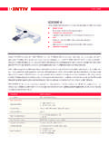
1 INSTALLATION guide . SCB-100. 100-Pin Shielded Desktop Connector Block This guide describes how to connect and use the NI SCB-100 with 100-Pin data acquisition (DAQ). devices. The SCB-100 is a Shielded Desktop accessory with 100 screw terminals, a cold-junction compensation temperature sensor for use with thermocouples, and a strain-relief bar for securing signal wires or cables. The SCB-100 connects to E Series MIO devices (NI 6025E, NI 6031E, NI 6033E, and NI 6071E), DIO devices (PCI-DIO-96, NI 6508, NI 6509, NI 6511, NI 6512, NI 6513, NI 6514, NI 6515, NI 6527, and NI 6528), TIO Series devices (NI 6624), or other products with a 100-Pin series Shielded D-type I/O Connector . Note To use the SCB-100 with a DIO or TIO Series device, you must change the default switch setting.
2 Refer to the Using the SCB-100 with DIO/TIO Devices section for more information. Figure 1 shows the SCB-100 Connector Block . 1. 2. 3. 9. 8 4. 5. 7. 6. 1 Quick Reference Label 4 Grounding Screw 7 Strain-Relief Hardware 2 Top Cover 5 100-Pin I/O Connector 8 Strain-Relief Screws 3 100-Pin Connector Screw 6 Base 9 SCB-100 Board Assembly Figure 1. SCB-100 Connector Block Contents What You Need to Get Started .. 2. Attaching the Quick Reference 2. Getting Started with the SCB-100 .. 2. Using the SCB-100 with DIO/TIO Devices .. 4. Using the SCB-100 with MIO Devices .. 5. Removing the Board .. 8. Soldering, Desoldering, and Cutting Via Traces on the SCB-100 9. 9. Where to Go for Support .. 10. What You Need to Get Started To set up and use your SCB-100, you need the following: SCB-100 100-Pin Shielded Connector Block kit, containing the SCB-100, SCB-100 quick reference label, and SCB-100 Installation guide 100-Pin DAQ device and device documentation SH100100 cable (part number 182853-0x) for E Series/MIO devices or SH100-100-F cable (part number 185095-0x) for DIO/TIO Series devices Phillips #1 and #2 screwdrivers 26 AWG wire Wire cutters Wire insulation strippers 1/8 in.
3 Flathead screwdriver Soldering iron and solder (optional). Long nose pliers (optional). Resistors and capacitors specific to your application (optional). Attaching the Quick Reference Label A quick reference label is included in the SCB-100 100-Pin Shielded Connector Block kit to show switch configurations and define screw terminal pinouts for E Series devices. Place the label on the inside of the top cover, as shown in Figure 1. For a PDF of the E Series quick reference label, refer to the KnowledgeBase document, Where Can I. Find .PDF Copies of the SCB-100 and/or SCB-68 Quick Reference Label Stickers?. To access this KnowledgeBase, go to and enter the info code rdwpdf. For DIO, TIO Series, or other 100-Pin device signal information, refer to your device documentation.
4 Getting Started with the SCB-100. The following cautions contain important safety information concerning hazardous voltages and Connector blocks. Caution To avoid electrical shock, do not remove equipment covers or shields unless you are qualified to do so. If signal wires are connected to the SCB-100, hazardous voltages may exist even when the equipment is turned off. Before removing the cover, disconnect the AC power or any live circuit from the Connector Block . The chassis ground terminals on your SCB-100 are for grounding high-impedance sources such as a floating source (1 mA maximum). Do not use these terminals as safety earth grounds. Do not connect hazardous voltages ( 42 Vpk/60 VDC). National Instruments is not liable for damage or injury resulting from such misuse.
5 SCB-100 Installation guide 2 Figure 2 shows the SCB-100 board parts locator diagram. 1 2 3. 3. 4. 5. 6 6. 9. 6. 3 7 3. 8. 1 Switches S4, S5, and S6 6 Screw Terminals 2 100-Pin I/O Connector 7 Breadboard Area 3 Board Mount Screw Hole 8 Vias Shorted to Screw Terminal 4 Signal Accessory Power LED (DS1) 9 Cold-Junction Compensation Temperature Sensor 5 Switches S1, S2, and S3. Figure 2. SCB-100 Board Parts Locator Diagram To get started with the SCB-100, complete the following steps while referring to Figures 1 and 2. 1. Disconnect the 100-Pin cable from the SCB-100, if connected. 2. Remove the grounding screws on either side of the top cover with a Phillips #1 screwdriver. Open the top cover. 3. Configure switches for the signal types you are using, as explained in the Using the SCB-100 with DIO/TIO Devices section or the Using the SCB-100 with MIO Devices section.
6 4. Adjust the strain-relief hardware. a. Loosen the strain-relief screws with a Phillips #2 screwdriver and slide the signal wires through the front panel strain-relief opening. b. If you are connecting multiple signals, remove the top strain-relief bar. 5. Add insulation or padding if necessary. National Instruments Corporation 3 SCB-100 Installation guide 6. Connect the wires to the screw terminals by stripping 1/4 in. of insulation, inserting the wires into the screw terminals, and tightening the screws. 7. Reinstall strain-relief (if removed) and tighten the strain-relief screws. 8. Close the top cover. 9. Reinsert the grounding screws to ensure proper shielding. 10. Connect the SCB-100 to the 100-Pin Connector . Using the SCB-100 with DIO/TIO Devices DIO devices, TIO Series devices, and DAQ devices without analog input functionality must use the DIO/passthrough mode.
7 Move the switches to the DIO/passthrough mode switch setting as shown in Table 1. Table 1. DIO/TIO Series Device Switch Setting Switch Setting Description DIO/passthrough mode Move switches S1, S2, S3, S4, S5, and S6 to the S1 positions shown at left. In this mode: S2 All 100 signals from the DAQ device connect directly to screw terminals. S3 The signal accessory power LED (DS1) does not light in this configuration. S6 S5 S4. Refer to Figure 3 for a detailed diagram. DAQ Device SH100-100 Cable SCB-100 Screw Terminal 1. 1. Refer to 2. Your Device 2. Documentation for Device Signal Information 99. 99. 100. 100. NC. LED. Temperature NC. Sensor NC. S1. S2. S3. S6 S5 S4. Figure 3. DIO/Passthrough Mode Switch Setting SCB-100 Installation guide 4 Using the SCB-100 with MIO Devices You can take measurements with the SCB-100 and MIO DAQ devices, such as E Series, in a number of ways.
8 The SCB-100 has a temperature sensor for cold-junction compensation to accommodate thermocouples. Switches S4, S5, and S6 configure the temperature sensor for different analog input settings. Table 2 shows the different switch settings for MIO DAQ devices. Table 2. MIO Device Switch Settings Switch Setting Description MIO with disabled temperature sensor mode (default configuration) Move switches S1, S2, S3, S4, S5, and S6 to the positions shown at left. In this mode: S1 The temperature sensor is not used. S2 AI 0 and AI 8 are available on screw terminals. S3. The signal accessory power LED (DS1) lights when the MIO device is S6 S5 S4. powered on and connected to the SCB-100. Refer to Figure 4 for a detailed diagram. MIO with single-ended temperature sensor mode Move switches S1, S2, S3, S4, S5, and S6 to the positions shown at left.
9 In this mode: S1. The temperature sensor can be read using AI 0 in referenced single-ended (RSE) mode. S2. S3 AI 8 is available on a screw terminal. S6 S5 S4 The signal accessory power LED (DS1) lights when the MIO device is powered on and connected to the SCB-100. Refer to Figure 4 for a detailed diagram. MIO with differential temperature sensor mode Move switches S1, S2, S3, S4, S5, and S6 to the positions shown at left. In this mode: S1. S2. The temperature sensor can be read using AI 0 and AI 8 in differential mode. S3 The signal accessory power LED (DS1) lights when the MIO device is S6 S5 S4 powered on and connected to the SCB-100. Refer to Figure 4 for a detailed diagram. DIO/passthrough mode You can use DIO/passthrough mode with an MIO.
10 S1. device. S2. S3 Refer to Table 1 for configuration information and Figure 3 for a detailed S6 S5 S4 diagram. National Instruments Corporation 5 SCB-100 Installation guide DAQ Device SH100-100 Cable SCB-100 Screw Terminal 34 34. +5 V. Refer to LED. Your Device Documentation for Device Signal Information 3 S5 Temperature AI 0. Sensor 3. 4 S4. AI 8. 4. 1. 1. 2 2. 5 5. Other 6 6. Pins 99 99. 100. 100. S1. S2. S3. S6. Figure 4. MIO Device Modes Switch Settings Temperature Sensor Output and Accuracy The SCB-100 temperature sensor outputs 10 mV/ C and has an accuracy of C. You also can determine the temperature using the following formulas: TC = 100 Vt TK = TC + 9. T F = --- T C + 32. 5. where Vt is the temperature sensor output voltage.
